|
|
|
PDF RClamp0564P Data sheet ( Hoja de datos )
| Número de pieza | RClamp0564P | |
| Descripción | ESD Protection | |
| Fabricantes | Semtech | |
| Logotipo | ||
Hay una vista previa y un enlace de descarga de RClamp0564P (archivo pdf) en la parte inferior de esta página. Total 8 Páginas | ||
|
No Preview Available !
RClamp0564P
Femto Farad RailClamp®
4-Line, 170fF ESD Protection
PROTECTION PRODUCTS
Description
RClamp®0564P is an ultra low capacitance ESD
protection device specifically designed to protect high-
speed differential lines. It offers desirable characteristics
for board level protection including fast response time,
low operating and clamping voltage, and no device
degradation
RClamp0564P features extremely good ESD protection
characteristics highlighted by low peak ESD clamping
voltage, and high ESD withstand voltage (+/-10kV
contact per IEC 61000-4-2). RClamp0564P is designed
to minimize both the ESD peak clamping and the TLP
clamping. Package inductance is reduced at each
pin resulting in lower peak ESD clamping voltage.
RClamp0564P has a typical capacitance of 0.17pF
allowing it to be used in high bandwidth applications
such as HDMI 2.0 4K/2K, Thunderbolt, and USB 3.1. Each
device will protect four high-speed data lines operating
up to 5 volts.
RClamp0564P is in a 5-pin SGP2010N5 package
measuring 2.0 x 1.0mm with a nominal height of
0.60mm. The leads have a nominal pin-to-pin pitch of
0.40mm. Flow- through package design simplifies PCB
layout and maintains signal integrity on high-speed lines.
Features
• High ESD Withstand Voltage
IEC 61000-4-2 (ESD) 10kV (contact)
• Ultra-Low Capacitance: 0.17pF Typical
• Very Small PCB Area
• Protects Four High-Speed Data Lines
• Working Voltage: 5V
• Low Dynamic Resistance: 0.65 Ohms
• Large Operating Bandwidth: 12GHz
• Solid-State Silicon-Avalanche Technology
Mechanical Characteristics
• SGP2010N5 Package
• Pb-Free, Halogen Free, RoHS/WEEE Compliant
• Nominal Dimensions: 2.0 x 1.0 x 0.60 mm
• Lead Pitch: 0.40mm
• Lead Finish: NiPdAu
• Marking : Marking Code
• Packaging : Tape and Reel
Applications
• HDMI 1.4, HDMI1.4b and HDMI 2.0
• USB 3.0 and USB 3.1
• USB Type-C
• Thunderbolt
• MIPI / MDDI
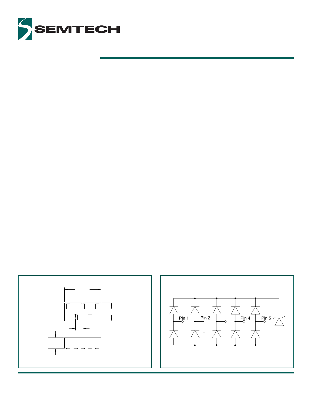
Nominal Dimensions
Schematic
2.00
12
1.00
0.40 BSC
0.60
Nominal Dimensions in mm
RClamp0564P
Final Datasheet
July 22, 2015
Rev 3.0
www.semtech.com
Pin 3
GND
1
Semtech
1 page 
Applications Information
Assembly Guidelines
The small size of this device means that some care must
be taken during the mounting process to insure reliable
solder joints. The figure at the right details Semtech’s
recommended mounting pattern. Recommended
assembly guidelines are shown in Table 1. Note that
these are only recommendations and should serve only
as a starting point for design since there are many factors
that affect the assembly process. Exact manufacturing
parameters will require some experimentation to get the
desired solder application. Semtech’s recommended
mounting pattern is based on the following design
guidelines:
Land Pattern
The recommended land pattern follows IPC standards and is
designed for maximum solder coverage. Detailed dimensions
are shown elsewhere in this document.
Solder Stencil
Stencil design is one of the key factors which will determine
the volume of solder paste which is deposited onto the land
pad. The area ratio of the stencil aperture will determine how
well the stencil will print. The area ratio takes into account the
aperture shape, aperture size, and stencil thickness. An area
ratio of 0.70 – 0.75 is preferred for the subject package. The
area ratio of a rectangular aperture is given as:
Area Ratio = (L * W )/ (2 * (L + W) * T)
Where:
L = Aperture Length
W = Aperture Width
T = Stencil Thickness
Semtech recommends a stencil thickness of 0.100mm for
this device. The stencil should be laser cut with electro-
polished finish. The stencil should have a positive taper of
approximately 5 degrees. Electro polishing and tapering
the walls results in reduced surface friction and better paste
release. For small pitch components, Semtech recommends
a square aperture with rounded corners for consistent solder
release. Due to the small aperture size, a solder paste with
Type 4 or smaller particles are recommended.
Recommended Mounting Pattern
0.200
0.400
0.025
0.650
0.025
1.000
0.300
0.200
2.000
All Dimensions are in mm.
0.800
Land Pad.
Stencil opening
Component
Table 1 - Recommended Assembly Guidelines
Assembly Parameter
Recommendation
Solder Stencil Design
Laser Cut, Electro-Polished
Aperture Shape
Rectangular with rounded
corners
Solder Stencil Thickness
0.100mm (0.004”)
Solder Paste Type
Type 4 size sphere or smaller
Solder Reflow Profile
Per JEDEC J-STD-020
PCB Solder pad Design
Non-Solder Mask Defined
PCB Pad Finish
OSP or NiAu
RClamp0564P
Final Datasheet
July 22, 2015
Rev 3.0
www.semtech.com
5
Semtech
5 Page | ||
| Páginas | Total 8 Páginas | |
| PDF Descargar | [ Datasheet RClamp0564P.PDF ] | |
Hoja de datos destacado
| Número de pieza | Descripción | Fabricantes |
| RClamp0564P | ESD Protection | Semtech |
| Número de pieza | Descripción | Fabricantes |
| SLA6805M | High Voltage 3 phase Motor Driver IC. |
Sanken |
| SDC1742 | 12- and 14-Bit Hybrid Synchro / Resolver-to-Digital Converters. |
Analog Devices |
|
DataSheet.es es una pagina web que funciona como un repositorio de manuales o hoja de datos de muchos de los productos más populares, |
| DataSheet.es | 2020 | Privacy Policy | Contacto | Buscar |