|
|
|
PDF RClamp0524PQ Data sheet ( Hoja de datos )
| Número de pieza | RClamp0524PQ | |
| Descripción | 4-Line Surge and ESD Protection | |
| Fabricantes | Semtech | |
| Logotipo | ||
Hay una vista previa y un enlace de descarga de RClamp0524PQ (archivo pdf) en la parte inferior de esta página. Total 10 Páginas | ||
|
No Preview Available !
RClamp0524PQ
Low Capacitance RailClamp®
4-Line Surge and ESD Protection
PROTECTION PRODUCTS
Description
RailClamp® TVS arrays are ultra low capacitance ESD
protection devices designed to protect high speed data
interfaces. This series has been speci cally designed to
protect sensitive components which are connected to
high-speed data and transmission lines from overvoltage
caused by ESD (electrostatic discharge), CDE (Cable
Discharge Events), and EFT (electrical fast transients).
RClamp0524PQ has a typical capacitance of only 0.3 pF
between I/O pins. This allows it to be used on circuits
operating in excess of 3GHz with no signi cant signal
attenuation. ESD characteristics are highlighted by high
ESD withstand voltage (+/-15kV per IEC 61000-4-2) and
low dynamic resistance (0.43 Ohms typical). Each device
will protect four lines operating at 5 volts
RClamp0524PQ is in a 10-pin SLP2510P8 package and
is quali ed to AEC-Q100, Grade 1 (-40 to +125 oC) for
automotive applications. It measures 2.5 x 1.0 mm with
a nominal height of only 0.58 mm. The leads are nished
with lead-free NiPdAu. The ow- through package design
simpli es PCB layout.
Features
• Transient Protection to
s IEC 61000-4-2 (ESD) 25kV (Air), 15kV (Contact)
s IEC 61000-4-4 (EFT) 4kV (5/50ns)
s IEC 61000-4-5 (Lightning) 5A (8/20µs)
s ISO-10605 (ESD) 20kV (Air), 12kV (Contact)
• Quali ed to AEC-Q100, Grade 1
• Protects four High-Speed Data Lines
• Working Voltage: 5V
• Low Capacitance: 0.8 pF Maximum (I/O to GND)
• Dynamic Resistance: 0.43 Ohms (Typ)
• Solid-State Silicon-Avalanche Technology
Mechanical Characteristics
• SLP2510P8 Package
• Pb-Free, Halogen Free, RoHS/WEEE Compliant
• Nominal Dimensions: 2.5 x 1.0 x 0.58 mm
• Lead Finish: NiPdAu
• Molding Compound Flammability Rating: UL 94V-0
• Marking : Marking Code + Date Code
• Packaging : Tape and Reel
Applications
• Automotive Applications
• Industrial Equipment
• HDMI
• Digital Visual Interface
• MDDI Ports
• PCI Express
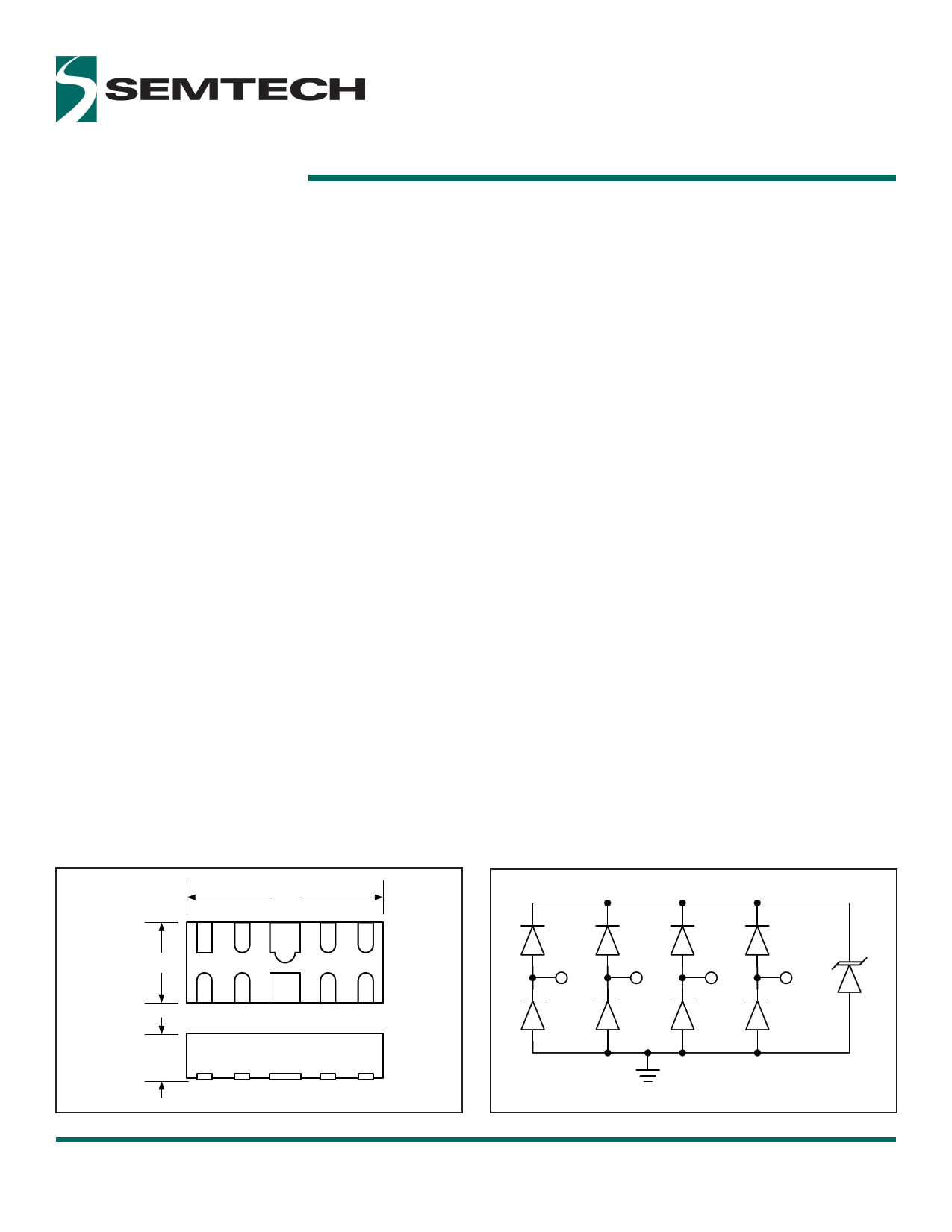
Nominal Dimension
!,"$
#,$$
Functional Schematic
&$+%
$,"%
!"#$ %.#. $
Nominal Dimensions in mm
RClamp0524PQ
Final Datasheet
Revision date
Rev 2.0
June 22, 2015
www.semtech.com
A
*.0
Device Schematic
%$+ @6&6
1 of 10
Semtech
1 page 
Applications Information
Assembly Guidelines
The small size of this device means that some care must
be taken during the mounting process to insure reliable
solder joint. The gure at the right details Semtech’s rec-
ommended mounting pattern. Recommended assembly
guidelines are shown in Table 2. Note that these are only
recommendations and should serve only as a starting
point for design since there are many factors that a ect
the assembly process. Exact manufacturing parameters
will require some experimentation to get the desired
solder application. Semtech’s recommended mounting
pattern is based on the following design guidelines:
$,!$
Recommended Stencil Design
$,"$
$,!"
)1( *
$,!$
(1( *
#,""
$,5C"
Land Pattern
The recommended land pattern follows IPC standards
and is designed for maximum solder coverage. Detailed
dimensions are shown elsewhere in this document.
Solder Stencil
Stencil design is one of the key factors which will
determine the volume of solder paste which is deposited
onto the land pad. The area ratio of the stencil aperture
will determine how well the stencil will print. The area
ratio takes into account the aperture shape, aperture
size, and stencil thickness. The area ratio of a rectangular
aperture is given as:
Area Ratio = (L * W )/ (2 * (L + W) * T)
Where:
L = Aperture Length
W = Aperture Width
T = Stencil Thickness
Semtech recommends a stencil thickness of 0.100mm
- 0.125mm for this device. The stencil should be laser
cut with electro-polished nish. The stencil should have
a positive taper of approximately 5 degrees. Electro
polishing and tapering the walls results in reduced
surface friction and better paste release. Due to the
small aperture size, a solder paste with Type 4 or smaller
particles is recommended. Assuming a 125um thick
stencil, the aperture dimensions shown will yield an area
ratio of 0.72 for the small pads and 1.25 for the large.
$,:$
!"#$ %.5. $
Table 2 - Recommended Assembly Guidelines
Assembly Parameter
Recommendation
Solder Stencil Design
Aperture Shape
Laser Cut, Electro-Polished
Rectangular
Solder Stencil Thickness 0.100mm (0.004”) -
0.125mm (0.005”)
Solder Paste Type
Solder Re ow Pro le
Type 4 size sphere or smaller
Per JEDEC J-STD-020
PCB Solder pad Design Non-Solder Mask De ned
PCB Pad Finish
OSP or NiAu
Design Recommendations for HDMI Protection
Adding external ESD protection to HDMI ports can
be challenging. First, ESD protection devices have an
inherent junction capacitance and adding even a small
amount of capacitance will cause the impedance of the
di erential pair to drop. Second, large packages and
land pattern requirements cause discontinuities that
adversely a ect signal integrity. The RClamp0524PQ
is speci cally designed for protection of high-speed
interfaces such as HDMI. It presents <0.4pF capacitance
between the pairs while being rated to handle >±8kV
ESD contact discharges (>±15kV air discharge) as
outlined in IEC 61000-4-2. Each device is in a leadless
SLP package that is less than 1.1mm wide. It is designed
such that the traces ow straight through the device.
The narrow package and ow-through design reduces
discontinuities and minimizes impact on signal integrity.
This becomes more critical as signal speeds increase.
RClamp0524PQ
Final Datasheet
Revision Date
Rev 2.0
June 22, 2015
www.semtech.com
5 of 10
Semtech
5 Page | ||
| Páginas | Total 10 Páginas | |
| PDF Descargar | [ Datasheet RClamp0524PQ.PDF ] | |
Hoja de datos destacado
| Número de pieza | Descripción | Fabricantes |
| RCLAMP0524P | (RCLAMP0522P / RCLAMP0524P) TVS Array | Semtech Corporation |
| RClamp0524PA | Ultra Low Capacitance TVS Arrays | Semtech Corporation |
| RClamp0524PQ | 4-Line Surge and ESD Protection | Semtech |
| Número de pieza | Descripción | Fabricantes |
| SLA6805M | High Voltage 3 phase Motor Driver IC. |
Sanken |
| SDC1742 | 12- and 14-Bit Hybrid Synchro / Resolver-to-Digital Converters. |
Analog Devices |
|
DataSheet.es es una pagina web que funciona como un repositorio de manuales o hoja de datos de muchos de los productos más populares, |
| DataSheet.es | 2020 | Privacy Policy | Contacto | Buscar |