|
|
|
PDF WS3230 Data sheet ( Hoja de datos )
| Número de pieza | WS3230 | |
| Descripción | High PF PSR Constant Current LED Driver | |
| Fabricantes | WINSEMI | |
| Logotipo | ||
Hay una vista previa y un enlace de descarga de WS3230 (archivo pdf) en la parte inferior de esta página. Total 7 Páginas | ||
|
No Preview Available !
WS3230
WS3230 High PF PSR Constant Current LED Driver
Features
� ±5% LED Current Accuracy
� Primary-side Sensing and Regulation Without
TL431 and Opto-coupler
� No Auxiliary Winding For Sensing And Supplying
� High Power Factor Correction
� Ultra low operating current
� LED Open/Short Circuit Protection
� CS Resistor Short Circuit Protection
� VCC over voltage protection & under voltage
lockout( UVLO)
� Over Temperature Protection
Applications
� GU10 LED driver
� LED spot light
� Other LED lighting
General Description
WS3230 is a high precision QR primary-side feedback
and regulation controller for LED lighting, optimized for
flyback converter with the output power less than 30W.
Since adopting primary sense and feedback control
technology, the secondary sense and feedback circuit is
eliminated. And WS3230 does not need the auxiliary
winding for sensing the output current and supplying the
chip. The low component counts and small system size
are realized.
Since using the high accurate current sense method,
WS3230 realizes ±5% accuracy of LED current along with
excellent line and load regulation.
WS3230 offers comprehensive protection including
Cycle-by-Cycle current limiting (OCP), LED open/short
circuit protection, CS resistor short circuit protection, VCC
UVLO,OVP and Clamp, and over temperature protection.
WS3230 is available in SOT23-5 package.
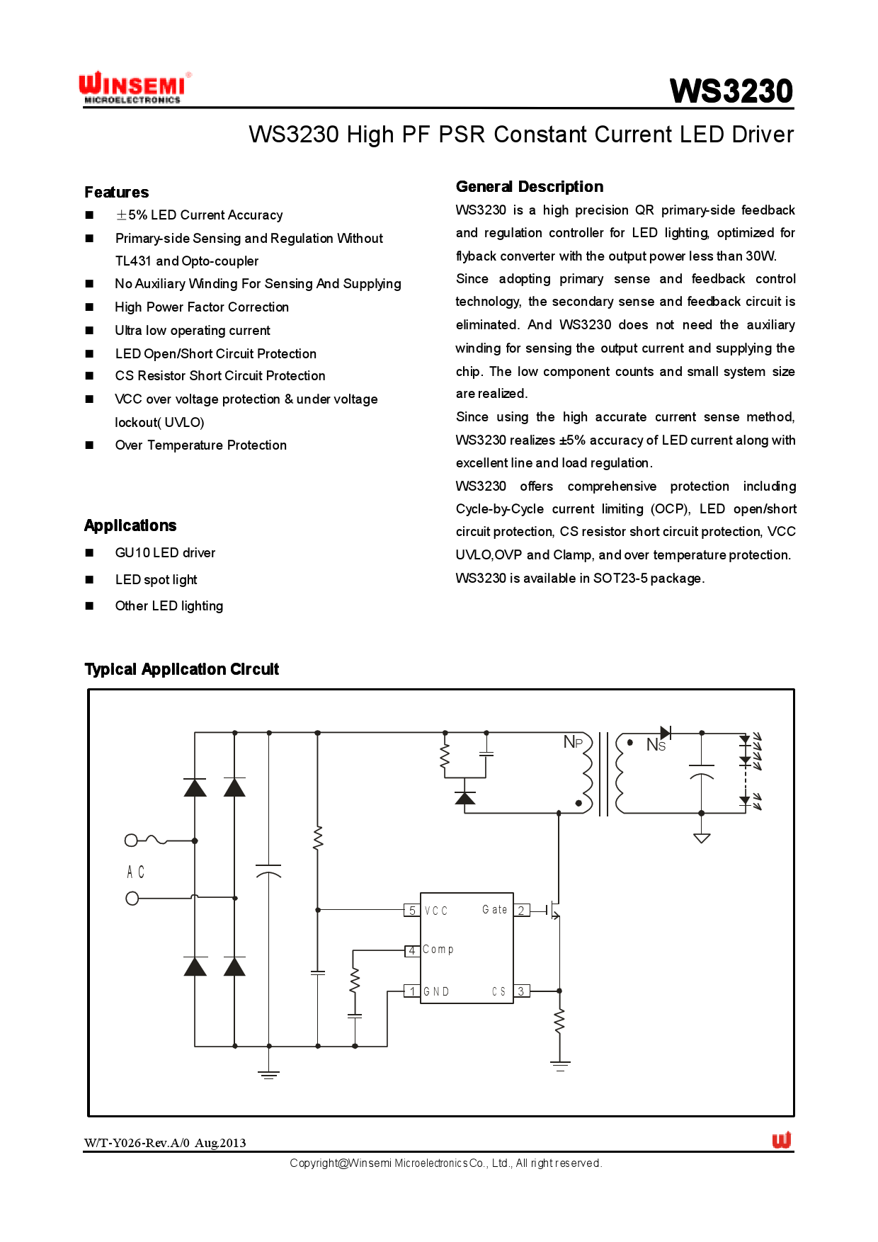
Typical Application Circuit
NP NS
AC
5 VCC
G ate 2
4 Comp
1 GND
CS 3
W/T-Y026-Rev.A/0 Aug.2013
Copyright@Winsemi Microelectronics Co., Ltd., All right r eserved.
1 page 
WS3230
Function Description
WS3230 is a high-integrated offline QR PSR controller,
optimized for low power LED driver. WS3230 operates in
primary-side sensing and regulation. Consequently,
opto-coupler and TL431 could be eliminated, thus reduce
the cost.
Startup Current
Startup current of WS3230 is designed to as low as 60uA.
The VCC capacitor will be charged through the start-up
resistor when the system is powered on. Once the VCC
voltage reaches the start-up threshold, the WS3230 will
start to switch. The WS3230 integrates a 15V zener for
VCC clamping. Due to the ultra-low operating current, the
auxiliary winding is not need to supply the IC.
Quasi-Resonant Operation
=(Vcs *Tons/T)*0.5*(Nps/Rcs)
=0.083*(Nps/Rcs)
Once the parameters of the transformer and the current
sense resistor Rcs is determined, so is the output current.
And the output current can be set by adjusting the current
sense resistor Rcs.
Internal pre-charge design for quick start up
After VCC exceeds UVLO_ON, Vcomp is pre-charged by
an internal current source. The PWM block will not start to
output PWM signals until Vcomp is over 0.45V. Such
design is meant to reduce the start up time. The voltage
pre-charged Vcomp in start-up procedure can be
programmed b y,
Vcom p=0.4V-300uA*Rcomp
Where Rcomp is the series resistor of Comp pin.
Quasi-Resonant switching mode is applied in WS3230.
When the voltage across drain and source of the primary
MOSFET is at voltage valley, the MOSFET would be
turned on, reducing the switching losses and improving
EMI performance.
CC Operation
Operation switching frequency
The frequency of WS3230 is decided by load condition
and QR mode. When the output power decreases, the
switching frequency can become rather high. The
maximum switching frequency in WS3230 is internally
limited to 120Khz.
WS3230 is designed to produce good CC control
characteristic. In DCM mode, the output current Io can be
represented b y,
Io=0.5*Ips*Tons/T
Where Ips is the peak current of the secondary side; Tons
is the turn on time of secondary side; T is the switching
period.
Ips=Ipp*Nps=(Vcs /Rcs)*Nps
Where Ipp is the primary peak current; Vcs is the voltage
on CS resistor; Rcs is primary current detection resistor;
Nps is the turns ratio of primary to secondary of the
flyback transformer. The relationship of Vcs, To ns and T is
controlled to be constant by internal circuit,
3*Vcs*Tons/T=0.5V. Thus, Io can be represented b y,
Io=0.5*(Vcs /Rcs)*Nps*Tons/T
Current Sensing and Leading Edge Blanking
Cycle-by-Cycle current limiting is offered in WS3230. The
switch current is detected by a sense resistor into the
sense pin. An internal leading edge blanking circuit chops
off the sense voltage spike at initial MOSFET on state due
to snubber diode reverse recovery so that the external RC
filtering on sense input is no longer required. The current
limit comparator is disabled and thus cannot turn off the
external MOSFET during the blanking period.
Protection Controls
Excellent system stability is achieved by the
comprehensive protection of WS3230. Including
Steady, keep you advance
5/7
5 Page | ||
| Páginas | Total 7 Páginas | |
| PDF Descargar | [ Datasheet WS3230.PDF ] | |
Hoja de datos destacado
| Número de pieza | Descripción | Fabricantes |
| WS3230 | High PF PSR Constant Current LED Driver | WINSEMI |
| WS3231 | High PF PSR Constant Current LED Driver | WINSEMI |
| WS3232 | High PF PSR Constant Current LED Driver | WINSEMI |
| Número de pieza | Descripción | Fabricantes |
| SLA6805M | High Voltage 3 phase Motor Driver IC. |
Sanken |
| SDC1742 | 12- and 14-Bit Hybrid Synchro / Resolver-to-Digital Converters. |
Analog Devices |
|
DataSheet.es es una pagina web que funciona como un repositorio de manuales o hoja de datos de muchos de los productos más populares, |
| DataSheet.es | 2020 | Privacy Policy | Contacto | Buscar |