|
|
|
PDF L9703D Data sheet ( Hoja de datos )
| Número de pieza | L9703D | |
| Descripción | OCTAL GROUND CONTACT MONITORING CIRCUIT | |
| Fabricantes | STMicroelectronics | |
| Logotipo | ||
Hay una vista previa y un enlace de descarga de L9703D (archivo pdf) en la parte inferior de esta página. Total 9 Páginas | ||
|
No Preview Available !
L9703
OCTAL GROUND CONTACT MONITORING CIRCUIT
. OPERATING DC SUPPLY VOLTAGE RANGE
5V TO 25V
. SUPPLY OVERVOLTAGE PULSE UP TO 40V
. VERY LOW STANDBY QUIESCENT CUR-
RENT 0.2mA
. INTERNAL CLAMPING DIODES AT CONTACT
INPUTS TO VS AND GND
. INPUT PULSE CURRENT CAPABILITY UP TO
+ 50mA ; – 75mA
. NOMINAL CONTACT CURRENT OF 10mA DE-
. FINED BY EXTERNAL CONTACT SERIES RE-
SISTORS RI N1–8
CONTACT STATUS MONITORING BY COM-
PARING THE RESISTANCE AT CONTACT
. SENSE INPUTS WITH THE INTERNAL REFER-
ENCE RESISTOR VALUE
HIGH IMMUNITY DUE TO RESISTANCE COM-
PARISON WITH HYSTERESIS
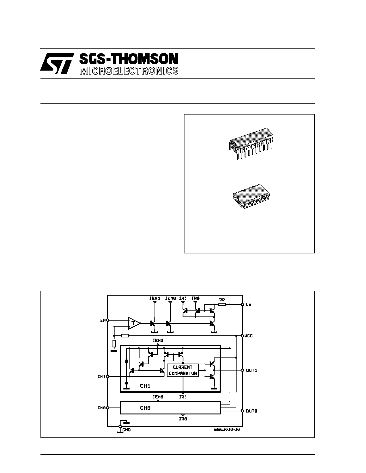
DIP-20
SO-20L
ORDERING NUMBERS : L9703 (DIP-20)
L9703D (SO-20L)
DESCRIPTION
The L9703 is a bipolar monolithic integrated cir-
cuit for monitoring the status of up to eight con-
tacts connected to GND.
It contains eight contact sense inputs and eight
microcomputer compatible three-state outputs.
BLOCK DIAGRAM
March 1992
1/9
1 page 
L9703
FUNCTIONAL DESCRIPTION
The L9703 circuit monitors the status of the contacts
connected to ground and through this series exter-
nal resistors RIN to the contact sense input pins. The
contacts equivalent circuit is supposed to be as
shown in fig. 2.
The L9703 circuit compares the input current with
the current through the internal reference resistor.
The device is designed to work with anexternal input
series resistor of RIN1-8 = 1kΩ. With this input resistor
the contact current, when the contact is closed and
the device activated (EN = LOW) is
VS - 2V
IIN = 1kΩ
(1)
For this calculation the limit value of the VS to IN
saturation voltage of 2V was considered so that the
lowest limit value of IIN is calculated in (1).
The function of the circuit can be demonstrated with
the transfer characteristics, showing the output
status as a function of the input resistor RI, shown
in figure 3. The input resistor is a sum of the RIN and
the contact resistance RCON orRCOFF, for the closed
contact :
RI = RIN + RCON,
(2)
and for the open contact :
RI = RIN + RCOFF.
(3)
The output goes HIGH when the input resistance in-
creases above5.3kΩ (typical value) and goes LOW,
when the input resistance decreases below 4kΩ
(typical value). The limit values of RI = 1.8KΩ for
LOW and RI = 20kΩ for HIGH implies that a contact
with RCON = 100Ω (at IIN = 10mA) will be recognized
as ON = LOW and a contact with RCOFF = 19kΩ will
be recognized as OFF = HIGH. These limits are
valid within the supply voltage range 6V ≤ VS ≤ 16V
and the ground potential difference of
∆VGND = 0,1V.
The internal clamping diodes at the contact moni-
toring inputs, togetherwith the external contacts se-
ries resistors RIN, allows the device to withstand
transientsat the contactconnection.The contactse-
ries resistor RIN limits the input current at the tran-
sient.
The dynamic behaviour of the circuit is defined by
the times tdo and tdTs. When the contact is open, the
input capacitor CIN must be charged through the re-
sistor RIN. In this case the total delay time may also
be influenced by the time constant RINCIN.
The delay time tdTs, when disabling the device, is de-
fined only by the internal circuitry. In both cases, an
external output capacitance less than 50pF is as-
sumed, the internal output capacitances of the
three-state buffers are less than 5pF.
Figure 2 : The Contact Sense Input Connection with the Contact Equivalent Circuit.
5/9
5 Page | ||
| Páginas | Total 9 Páginas | |
| PDF Descargar | [ Datasheet L9703D.PDF ] | |
Hoja de datos destacado
| Número de pieza | Descripción | Fabricantes |
| L9703 | OCTAL GROUND CONTACT MONITORING CIRCUIT | STMicroelectronics |
| L9703D | OCTAL GROUND CONTACT MONITORING CIRCUIT | STMicroelectronics |
| Número de pieza | Descripción | Fabricantes |
| SLA6805M | High Voltage 3 phase Motor Driver IC. |
Sanken |
| SDC1742 | 12- and 14-Bit Hybrid Synchro / Resolver-to-Digital Converters. |
Analog Devices |
|
DataSheet.es es una pagina web que funciona como un repositorio de manuales o hoja de datos de muchos de los productos más populares, |
| DataSheet.es | 2020 | Privacy Policy | Contacto | Buscar |