|
|
|
PDF IR3802MPBF Data sheet ( Hoja de datos )
| Número de pieza | IR3802MPBF | |
| Descripción | SYNCHRONOUS BUCK REGULATOR | |
| Fabricantes | International Rectifier | |
| Logotipo | ||
Hay una vista previa y un enlace de descarga de IR3802MPBF (archivo pdf) en la parte inferior de esta página. Total 21 Páginas | ||
|
No Preview Available !
PD-60356
IR3802MPBF
SupIRBuckTM
HIGHLY INTEGRATED 4A
WIDE-INPUT VOLTAGE, SYNCHRONOUS BUCK REGULATOR
Features
• Wide Input Voltage Range 2.5V to 21V
• Wide Output Voltage Range 0.6V to 12V
• Continuous 4A Load Capability
• 600kHz High Frequency Operation
• Programmable Over-Current Protection
• Hiccup Current Limit
• Precision Reference Voltage (0.6V)
• Programmable Soft-Start
• Pre-Bias Start-up
• Thermal Protection
• Thermally Enhanced Package
• Small Size 5mmx6mm QFN
• Pb-Free (RoHS Compliant)
Applications
Description
The IR3802 SupIRBuckTM is an easy-to-use, fully
integrated and highly efficient DC/DC regulator.
The onboard switching controller and MOSFETs
make the IR3802 a space-efficient solution,
providing accurate power delivery for low output
voltage applications.
The IR3802 operates from a single 4.5V to 14V
input supply and generates an output voltage
adjustable from 0.6V to 0.75*Vin at loads up to 4A.
A versatile regulator offering programmability of
startup time, power good threshold and current
limit, the IR3802’s fixed 600kHz switching
frequency allows the use of small external
components.
• Game Consoles
• Set-top Boxes
• Graphics Cards
• LCD TVs
• Desktop PCs
• Distributed Point-of-Loads
• Embedded Systems
• Computing Peripheral Voltage Regulators
The IR3802 also features important protection
functions, such as Pre-Bias startup, hiccup
current limit and thermal shutdown to provide the
required system level security in the event of fault
conditions.
11/04/08
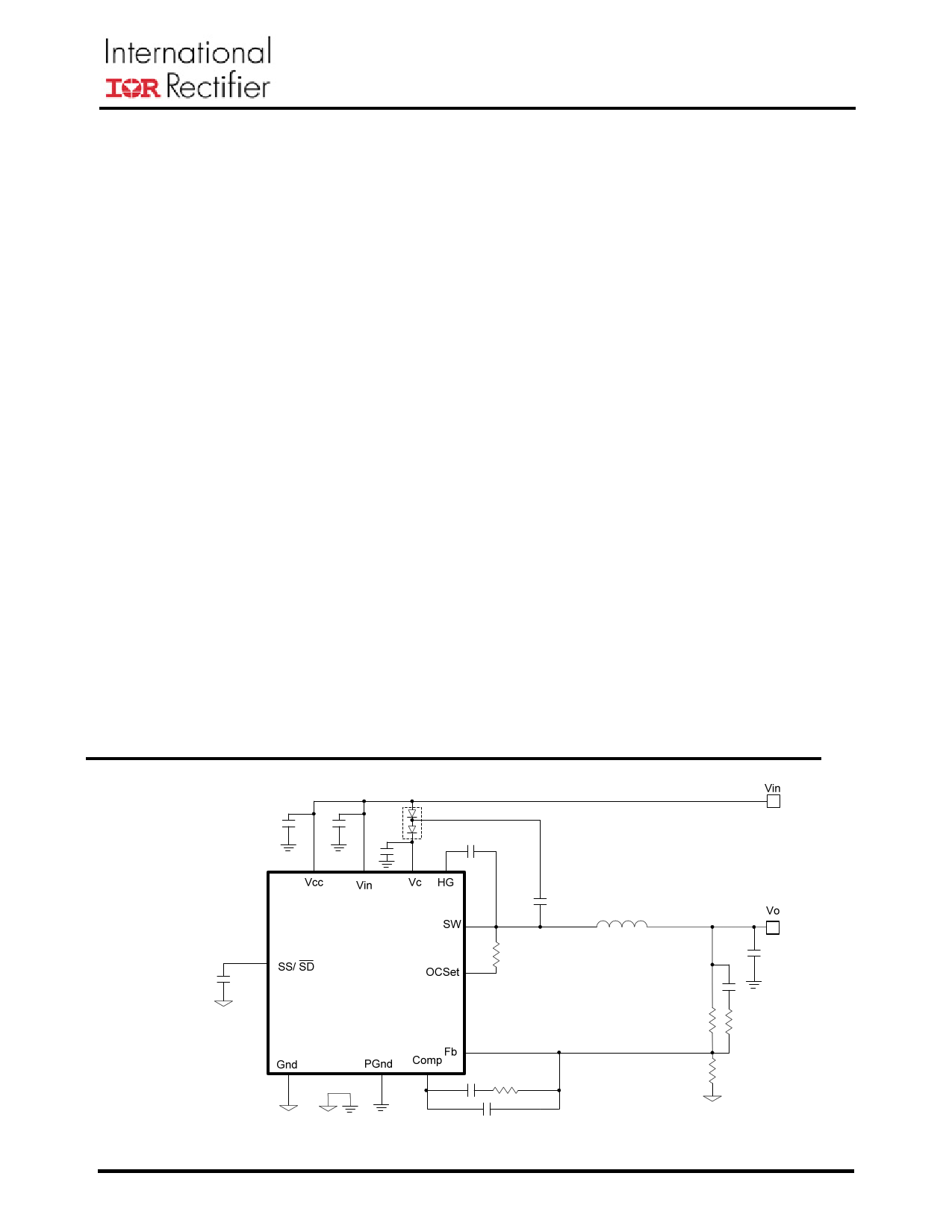
Fig. 1. Typical application diagram
1
1 page 
Recommended Operating Conditions
PD-60356
IR3802MPBF
Symbol
Vin
Vcc
Vc
Vo
Io Note1
Tj
Definition
Input Voltage
Supply Voltage
Supply Voltage
Output Voltage
Output Current
Junction Temperature
Min
2.5
4.5
Vin + 5V
0.6
0
-40
Max
21
14
28
12
4
125
Units
V
A
oC
Electrical Specifications
Unless otherwise specified, these specification apply over Vin=Vcc=Vc=12V, 0oC<Tj(Ic)<105oC.
Typical values are specified at Ta = 25oC.
Parameter
Power Loss
Power Loss
MOSFET Rds(on)
Top Switch
Bottom Switch
Reference Voltage
Feedback Voltage
Accuracy
Symbol
Ploss
Rds(on)_Top
Rds(on)_Bot
VFB
Supply Current
VCC Supply Current (Static)
VC Supply Current
(Static)
VCC Supply Current
(Dynamic)
VC Supply Current
(Dynamic)
Under Voltage Lockout
VCC-Start-Threshold
VCC-Stop-Threshold
VCC-Hysteresis
VC-Start-Threshold
VC-Stop-Threshold
VC-Hysteresis
ICC(Static)
IC(Static)
ICC(Dynamic)
IC(Dynamic)
VCC_UVLO(R)
VCC_UVLO(F)
VC_UVLO(R)
VC_UVLO(F)
Test Condition
Vcc=Vin=12V, Vc=24V, Vo=1.8V,
Io=4A, L=1.5uH, Note3
ID=6A, Tj(MOSFET)=25oC
ID=6A, Tj(MOSFET)=25oC
0oC<Tj<105oC
-40oC<Tj<105oC, Note2
SS=0V, No Switching
SS=0V, No Switching
SS=3V, Vc=24V, Vcc=Vin=12V.
Vo=1.8V, Io=0A
SS=3V, Vc=24V, Vcc=Vin=12V.
Vo=1.8V, Io=0A
Supply ramping up
Supply ramping down
Supply ramping up and down
Supply ramping up
Supply ramping down
Supply ramping up and down
Min TYP MAX Units
1.5 W
18 23
18 23
0.6
-1.5
-2.0
+1.5
+2.0
mΩ
V
%
%
10 13
4.5 7
15 22
15 22
mA
4.0
3.7
0.15
3.1
2.85
0.15
0.25
0.2
4.4
4.1
0.3
3.5
3.25
0.25
V
11/04/08
5
5 Page 
Application Information
Design Example:
The following example is a typical application for
the IR3802. The application circuit is shown in
page 17.
Vin = 12V,( 13 .2V, max )
Vo = 1.8V
Io = 4 A
ΔVo ≤ 30 mV
Fs = 600 kHz
Output Voltage Programming
Output voltage is programmed by reference
voltage and external voltage divider. The Fb pin
is the inverting input of the error amplifier, which
is internally referenced to 0.6V. The divider is
ratioed to provide 0.6V at the Fb pin when the
output is at its desired value. The output voltage
is defined by using the following equation:
Vo
= Vref
∗ ⎜⎜⎝⎛1 +
R8
R9
⎟⎟⎠⎞
--( 4 )
When an external resistor divider is connected to
the output as shown in figure 10.
IRIR33682042
Fb
VOUT
R8
R9
Fig. 10: Typical application of the IR3802 for
programming the output voltage
PD-60356
IR3802MPBF
Soft-Start Programming
The soft-start timing can be programmed by
selecting the soft-start capacitance value. The
start-up time of the converter can be calculated
by using:
CSS ≅ 20μA *Tstart --(1)
Where Tstart is the desired start-up time (ms)
For a start-up time of 11ms, the soft-start
capacitor will be 0.22uF.
Vc supply for single input voltage
To drive the high-side switch, it is necessary to
supply a gate voltage at least 4V greater than the
bus voltage. This is achieved by using a charge
pump configuration as shown in figure 11. This
method is simple and inexpensive. The operation
of the circuit is as follows: when the lower
MOSFET is turned on, the capacitor (C1) is
pulled down to ground and charges, up to VBUS
value, through the diode (D1). The bus voltage
will be added to this voltage when upper
MOSFET turns on in next cycle, and providing
supply voltage (Vc) through diode (D2). Vc is
approximately:
( )VC ≅ 2 ∗Vbus − VD1 +VD2 --(6 )
Capacitors in the range of 0.1uF are generally
adequate for most applications. The diodes must
be a fast recovery device to minimize the amount
of charge fed back from the charge pump
capacitor into VBUS. The diodes need to be able
to block the full power rail voltage, which is seen
when the high-side MOSFET is switched on. For
low-voltage application, schottky diodes can be
used to minimize forward drop aVcinross the diodes
at start up.
D1
D2
C1
Vc Vin
Equation (4) can be rewritten as:
R9
= R8
∗
⎜⎜⎝⎛
V
Vref
−VO ref
⎟⎟⎠⎞
--(5 )
For the calculated values of R8 and R9 see
feedback compensation section.
11/04/08
SW
PGnd
Fig. 11: CIRh3a8r0g2e pump circuit to generate
Vc voltage
11
11 Page | ||
| Páginas | Total 21 Páginas | |
| PDF Descargar | [ Datasheet IR3802MPBF.PDF ] | |
Hoja de datos destacado
| Número de pieza | Descripción | Fabricantes |
| IR3802MPBF | SYNCHRONOUS BUCK REGULATOR | International Rectifier |
| Número de pieza | Descripción | Fabricantes |
| SLA6805M | High Voltage 3 phase Motor Driver IC. |
Sanken |
| SDC1742 | 12- and 14-Bit Hybrid Synchro / Resolver-to-Digital Converters. |
Analog Devices |
|
DataSheet.es es una pagina web que funciona como un repositorio de manuales o hoja de datos de muchos de los productos más populares, |
| DataSheet.es | 2020 | Privacy Policy | Contacto | Buscar |