|
|
|
PDF BD90620HFP-C Data sheet ( Hoja de datos )
| Número de pieza | BD90620HFP-C | |
| Descripción | 1ch Step-Down Switching Regulator | |
| Fabricantes | ROHM Semiconductor | |
| Logotipo | ||
Hay una vista previa y un enlace de descarga de BD90620HFP-C (archivo pdf) en la parte inferior de esta página. Total 30 Páginas | ||
|
No Preview Available !
Datasheet
Input Voltage 3.5 V to 36 V
Output SW Current 4 A / 2.5A / 1.25A
1ch Step-Down Switching Regulator
BD906xx series
General Description
BD906xx series is a step-down switching regulator with
integrated POWER MOS FET and have the capability to
withstand high input voltage, providing a free setting
function of operating frequency with external resistor.
This switching regulator features a wide input voltage
range (3.5V to 36V, Absolute maximum 42V) and
operating temperature range (-40 °C to +125 °C).
Furthermore, an external synchronization input pin
enables synchronous operation with external clock.
Features
Integrated Pch POWER MOS FET
Low Dropout: 100 % ON Duty Cycle
External Synchronization Enabled
Soft Start Function: 1.38 ms (f = 500 kHz)
Current Mode Control
Over Current Protection
Low Supply Voltage Error Prevention
Thermal Shut Down Protection
Short Circuit Protection
High power HRP7 package mounted
Compact and High power HTSOP-J8 package
mounted
AEC-Q100 Qualified
Load dump up to 42V.
Applications
Automotive Battery Powered Supplies
(Cluster Panels, Car Multimedia)
Industrial / Consumer Supplies
Other electronic equipment
Key Specifications
Input Voltage Range:
3.5 V to 36 V
(Initial startup is over 3.9 V)
Output Voltage Range:
0.8V to VIN
Output Switch Current:
4 A / 2.5 A / 1.25 A (Max)
Switching Frequency:
50 kHz to 600 kHz
Reference Voltage Accuracy: ±2% (-40 °C to +125 °C)
Shutdown Circuit Current:
0 µA (Typ)
Operating Temperature Range: -40 °C to +125 °C
Package
HRP7
HTSOP-J8
W(Typ) x D(Typ) x H(Max)
9.395mm x 10.540mm x 2.005mm
4.90 mm x 6.00 mm x 1.00 mm
HRP7
HTSOP-J8
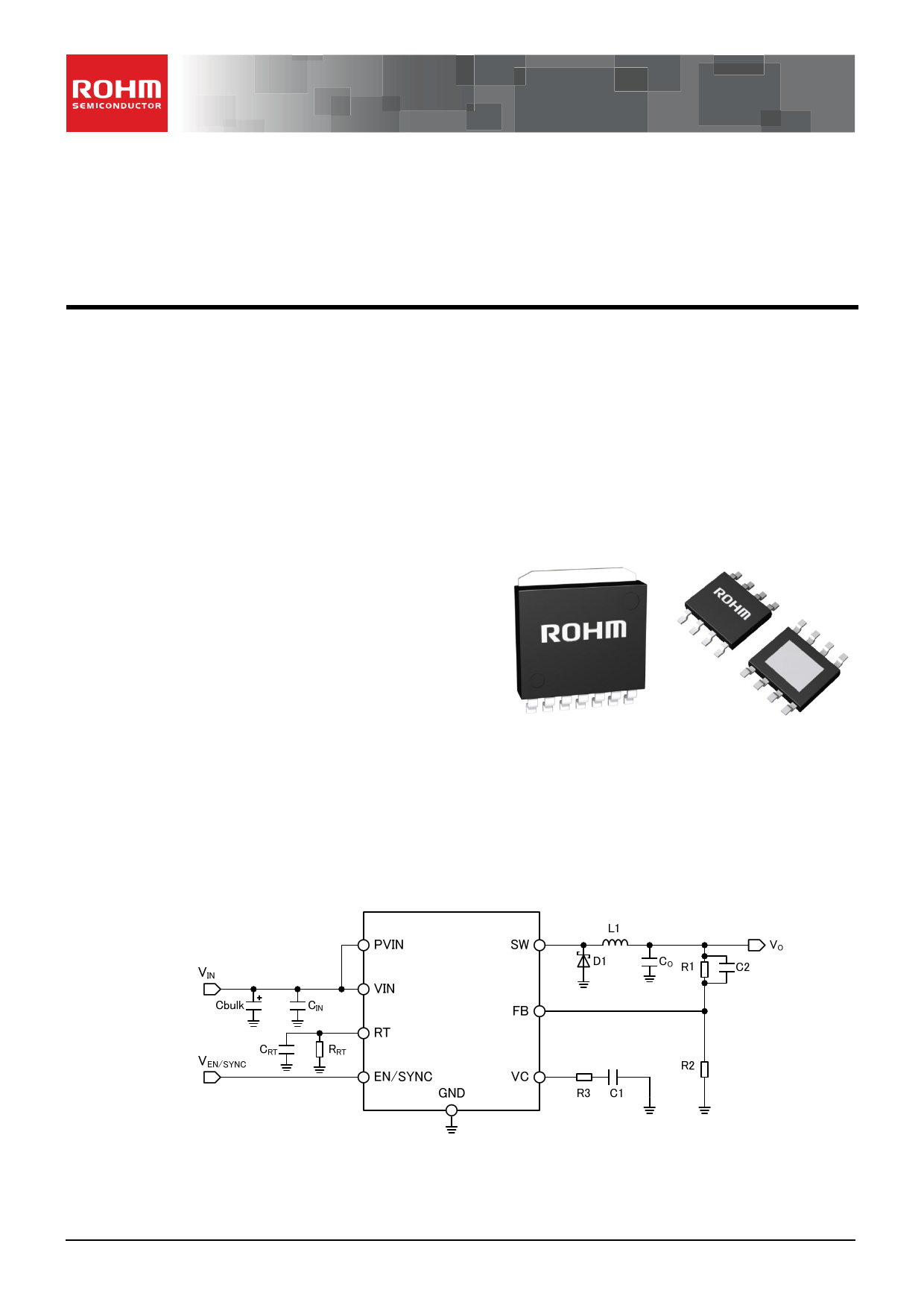
Typical Application Circuit
○Product structure:Silicon monolithic integrated circuit
www.rohm.com
© 2014 ROHM Co., Ltd. All rights reserved.
CVTSZ22111・14・001
○This product has no designed protection against radioactive rays
1/34
TSZ02201-0T1T0AL00130-1-2
21.Nov.2014 Rev.004
1 page 
BD906xx series
Datasheet
Absolute Maximum Ratings (Ta = 25 °C)
Parameter
Symbol
Rating
Unit
Power Supply Voltage
VIN、PVIN
-0.3 to +42
V
EN / SYNC Pin Voltage
VEN / SYNC
-0.3 to VIN
V
RT, VC, FB Pin Voltage
Power Dissipation(Note1)
HRP7(Note2)
HTSOP-J8(Note3)
VRT、VVC、VFB
PdHFP
PdEFJ
-0.3 to +7
6.98
3.10
V
W
Storage Temperature Range
Tstg
-55 to +150
°C
Maximum Junction Temperature
Tjmax
150 °C
(Note 1) Do not however exceed Pd.
(Note 2) Reduce by 56 mW / °C, when mounted on 4-layerPCB of 114.3mm × 76.2mm × 1.6mm
(2,3 inner layers and Copper foil area on the reverse side of PCB 74.2 mm × 74.2 mm)
(Note 3) Reduce by 25 mW / °C, when mounted on 4-layerPCB of 114.3mm × 76.2mm × 1.6mm
(2,3 inner layers and Copper foil area on the reverse side of PCB 74.2 mm × 74.2 mm)
Caution: Exceeding the absolute maximum rating for supply voltage, operating temperature or other parameters can result in damages to or destruction of the
chip. In this event it also becomes impossible to determine the cause of the damage (e.g. short circuit, open circuit, etc). Therefore, if any special
mode is being considered with values expected to exceed the absolute maximum ratings, implementing physical safety measures, such as adding
fuses, should be considered.
Recommended Operating Conditions
Parameter
Operating Power Supply Voltage (Note 1)
Symbol
VIN, PVIN
Limit
Min Max
3.5 36
Unit
V
Operating Temperature Range
Topr -40 +125 °C
BD90640HFP/EFJ-C
ISWopr40
-
4A
Output Switch Current (Note2)
BD90620HFP/EFJ-C
ISWopr20
-
2.5 A
BD90610EFJ-C
ISWopr10
- 1.25 A
Output Voltage
VO 0.8 VIN V
Min Pulse Width
TONMIN
250
-
ns
Oscillation Frequency
fSW 50 600 kHz
Oscillation Frequency Set Resistance
RRT 22 330 kΩ
Synchronous Operation Frequency Range
fSYNC
50 600 kHz
Synchronous Operation Frequency
fSYNC - RT -20 +20 %
External Clock Pulse Duty
DSYNC 10 90 %
Capacitance of Input Capacitor
CIN
2.4(Note 3)
-
µF
(Note 1) Initial startup is over 3.9 V.
(Note 2) The Limits include output DC current and output ripple current.
(Note 3) Ceramic capacitor is recommended. The capacitor value including temperature change, DC bias change, and aging change must be larger than
minimum value (Refer to p.14). Also, the IC might not function properly when the PCB layout or the position of the capacitor is not good. Please check
“Notes on the PCB Layout” on page 24.
www.rohm.com
© 2014 ROHM Co., Ltd. All rights reserved.
TSZ22111・15・001
5/34
TSZ02201-0T1T0AL00130-1-2
21.Nov.2014 Rev.004
5 Page 
BD906xx series
Datasheet
External Synchronizing Function
In order to activate the external synchronizing function, connect the frequency-setting resistor to the RT pin and then input a
synchronizing signal to the EN / SYNC pin.
The external synchronizing operation frequency is limited by the external resistance of RRT pin. The allowable setting limit is
within ±20 % of the oscillation frequency.
ex) When RRT is 27 kΩ (f = 500 kHz), the frequency range of the external synchronization is 400 kHz to 600 kHz.
Furthermore, the pulse wave’s LOW voltage should be under 0.8 V and the HIGH voltage over 2.6 V (when the HIGH voltage
is over 11 V the EN / SYNC input current increases), and the slew rate (rise and fall) under 20 V / µS. The duty of External
sync pulse should be configured between 10 % and 90%.
The frequency will synchronize with the external synchronizing operation frequency after three external sync pulses is
sensed.
Eternal SYNC Sample Circuit
www.rohm.com
© 2014 ROHM Co., Ltd. All rights reserved.
TSZ22111・15・001
11/34
TSZ02201-0T1T0AL00130-1-2
21.Nov.2014 Rev.004
11 Page | ||
| Páginas | Total 30 Páginas | |
| PDF Descargar | [ Datasheet BD90620HFP-C.PDF ] | |
Hoja de datos destacado
| Número de pieza | Descripción | Fabricantes |
| BD90620HFP-C | 1ch Step-Down Switching Regulator | ROHM Semiconductor |
| Número de pieza | Descripción | Fabricantes |
| SLA6805M | High Voltage 3 phase Motor Driver IC. |
Sanken |
| SDC1742 | 12- and 14-Bit Hybrid Synchro / Resolver-to-Digital Converters. |
Analog Devices |
|
DataSheet.es es una pagina web que funciona como un repositorio de manuales o hoja de datos de muchos de los productos más populares, |
| DataSheet.es | 2020 | Privacy Policy | Contacto | Buscar |