|
|
|
PDF X9318 Data sheet ( Hoja de datos )
| Número de pieza | X9318 | |
| Descripción | Digitally Controlled Potentiometer | |
| Fabricantes | Intersil | |
| Logotipo | ||
Hay una vista previa y un enlace de descarga de X9318 (archivo pdf) en la parte inferior de esta página. Total 10 Páginas | ||
|
No Preview Available !
®
Data Sheet
September 14, 2005
X9318
FN8184.1
Digitally Controlled Potentiometer
(XDCP™)
FEATURES
• Solid-state potentiometer
• 3-wire serial interface
• Terminal voltage, 0 to +8V
• 100 wiper tap points
—Wiper position stored in nonvolatile memory
and recalled on power-up
• 99 resistive elements
—Temperature compensated
—End to end resistance range ± 20%
• Low power CMOS
—VCC = 5V
—Active current, 3mA max.
—Standby current, 1mA max.
• High reliability
—Endurance, 100,000 data changes per bit
—Register data retention, 100 years
• RTOTAL value = 10kΩ
• Packages
—8 Ld SOIC and DIP
• Pb-free plus anneal available (RoHS compliant)
APPLICATIONS
• LCD bias control
• DC bias adjustment
• Gain and offset trim
• Laser diode bias control
• Voltage regulator output control
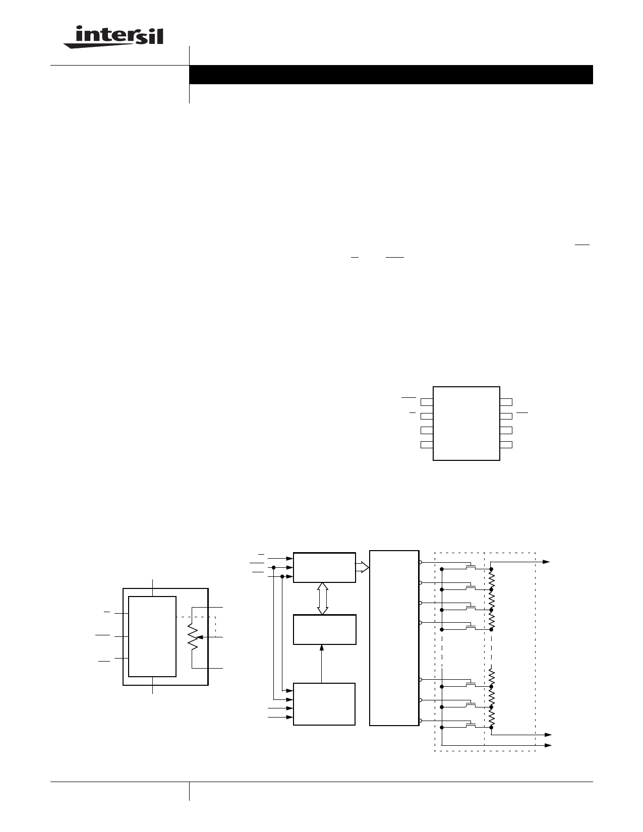
DESCRIPTION
The Intersil X9318 is a digitally controlled potentiometer
(XDCP). The device consists of a resistor array, wiper
switches, a control section, and nonvolatile memory.
The wiper position is controlled by a 3-wire interface.
The potentiometer is implemented by a resistor array
composed of 99 resistive elements and a wiper switch-
ing network. Between each element and at either end
are tap points accessible to the wiper terminal. The
position of the wiper element is controlled by the CS,
U/D, and INC inputs. The position of the wiper can be
stored in nonvolatile memory and then be recalled
upon a subsequent power-up operation.
The device can be used as a three-terminal potentiome-
ter for voltage control or as a two-terminal variable resis-
tor for current control in a wide variety of applications.
PIN CONFIGURATION
DIP/SOIC
INC
U/D
RH
VSS
18
2 X9318 7
36
45
VCC
CS
RL
RW
BLOCK DIAGRAM
VCC (Supply Voltage)
Up/Down
(U/D)
Increment
(INC)
Device Select
(CS)
Control
and
Memory
VSS (Ground)
General
U/D
INC
CS
RH
RW
RL
VCC
VSS
Up/Down
Counter
7-Bit
Nonvolatile
Memory
Store and
Recall
Control
Circuitry
99
98
97
One 96
of
One
Hundred
Decoder
2
1
0
Wiper
Switches
Resistor
Array
Detailed
RH
RL
RW
1
CAUTION: These devices are sensitive to electrostatic discharge; follow proper IC Handling Procedures.
1-888-INTERSIL or 1-888-468-3774 | Intersil (and design) is a registered trademark of Intersil Americas Inc.
XDCP is a trademark of Intersil Americas Inc. Copyright Intersil Americas Inc. 2005. All Rights Reserved
All other trademarks mentioned are the property of their respective owners.
1 page 
X9318
A.C. OPERATING CHARACTERISTICS
(VCC = 5V ± 10%, TA = Full Operating Temperature Range unless otherwise stated)
Symbol
Parameter
Min.
Limits
Typ.(4)
tCl
tlD(5)
tDI(5)
tlL
tlH
tlC
tCPHS
tCPHNS(5
)
CS to INC setup
INC HIGH to U/D change
U/D to INC setup
INC LOW period
INC HIGH period
INC inactive to CS inactive
CS deselect time (STORE)
CS deselect time (NO STORE)
100
100
1
1
1
1
20
1
tIW
tCYC
tR, tF(5)
tPU(5)
tR VCC(5)
INC to RW change
INC cycle time
INC input rise and fall time
Power-up to wiper stable
VCC power-up rate
100
4
0.2
Max.
500
500
500
50
Unit
ns
ns
µs
µs
µs
µs
ms
µs
µs
µs
µs
µs
V/ms
POWER-UP AND DOWN REQUIREMENTS
The recommended power-up sequence is to apply VCC/VSS first, then the potentiometer voltages. During power-up,
the data sheet parameters for the DCP do not fully apply until 1 millisecond after VCC reaches its final value. The VCC
ramp spec is always in effect. In order to prevent unwanted tap position changes, or an inadvertant store, bring the
CS and INC high before or concurrently with the VCC pin on powerup.
A.C. TIMING
CS
tCI
INC
tCYC
tIL tIH
tIC
tID tDI
tCPHS
90% 90%
10%
tCPHNS
tF tR
U/D
tIW
RW
MI (3)
5 FN8184.1
September 14, 2005
5 Page | ||
| Páginas | Total 10 Páginas | |
| PDF Descargar | [ Datasheet X9318.PDF ] | |
Hoja de datos destacado
| Número de pieza | Descripción | Fabricantes |
| X9312 | E2POT Nonvolatile Digital Potentiometer | Xicor |
| X9312 | Terminal Voltage 0V to 15V | Intersil Corporation |
| X9313 | E2POT Nonvolatile Digital Potentiometer | Xicor |
| X9313 | Digitally Controlled Potentiometer | Intersil Corporation |
| Número de pieza | Descripción | Fabricantes |
| SLA6805M | High Voltage 3 phase Motor Driver IC. |
Sanken |
| SDC1742 | 12- and 14-Bit Hybrid Synchro / Resolver-to-Digital Converters. |
Analog Devices |
|
DataSheet.es es una pagina web que funciona como un repositorio de manuales o hoja de datos de muchos de los productos más populares, |
| DataSheet.es | 2020 | Privacy Policy | Contacto | Buscar |