|
|
|
PDF GA3216 Data sheet ( Hoja de datos )
| Número de pieza | GA3216 | |
| Descripción | Pre-configured DSP System | |
| Fabricantes | ON Semiconductor | |
| Logotipo | ||
Hay una vista previa y un enlace de descarga de GA3216 (archivo pdf) en la parte inferior de esta página. Total 16 Páginas | ||
|
No Preview Available !
FOUNDATION GA3216
Pre-configured DSP System
for Hearing Aids
Description
The Foundation GA3216 hybrid is a trimmer−configurable DSP
system based on a two−channel compression circuit. It can efficiently
replace traditional hearing−aid compression circuits without
compromising fundamental performance requirements.
A trimmer interface supports manual circuit configuration. It
continuously monitors trimmer positions and translates them into the
hearing−aid parameters of choice. A serial data interface provides full
programmability at the factory and in the field.
The Foundation GA3216 includes in−channel squelch to attenuate
microphone and circuit noise in quiet environments. It also includes
low−distortion compression limiting and programmable high and low
cut filters, as well as five configurable equalization filters. Unused
blocks can be powered down to save battery current, for example,
when using the device in single−channel mode.
The Foundation GA3216 Hybrid code programmed into the
GC5020 controller chip is ‘1’.
Features
• Efficient, High Fidelity 1 or 2−Channel WDRC Signal Processing
• Fully Programmable via Serial Data Interface
• High−Fidelity Audio Quality
• Four Trimmer Inputs plus Volume Control
• Flexible Trimmer/Parameter Assignments
• Optional Two−Terminal or Three−Terminal Trimmers
• Choice of Wideband or Independent 2−Channel Level Detection
• Choice of Two Strategies for AGC−I Parametric Adjustment
• 6, 12 or 24 dB/Octave Band Split Filter or Configurable as
Single−Channel Compressor
• In−Channel, Low Level Squelch Control (1:2 Expansion)
• Output Compression Limiting (AGC−O)
• Flexible Pre− and Post−Emphasis Filters
• Four Independent Memories
• Pulse−Density−Modulated Output Stage Drives Zero−Bias
2−Terminal Receivers
• High-Power Drive Capability
• Unused Blocks can be Powered Down
• thinSTAX® Packaging
• Also Available as E1 RoHS Compliant Hybrid
thinSTAX Packaging
• Hybrid Typical Dimensions:
0.190 x 0.123 x 0.060 in.
(4.82 x 3.12 x 1.52 mm)
www.onsemi.com
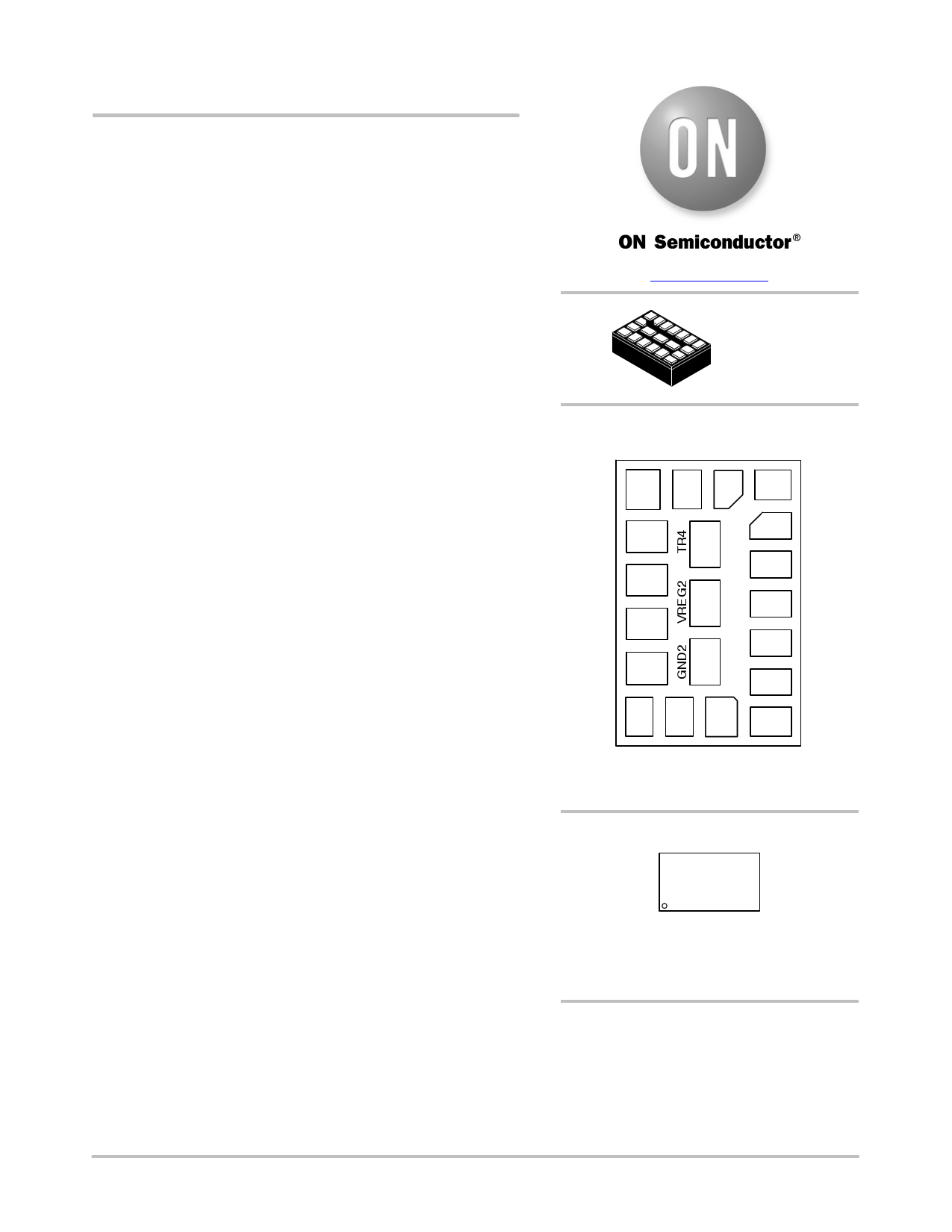
20 PAD
HYBRID
CASE TBD
MGND
MS2
MS
SDA
VB
PAD CONNECTION
IN T
15 16 17
1
14 18
13
19
12
11 20
2
3
4
5
6
VBP 10
9
8
7
OUT− OUT+
(Bottom View)
VREG
TR1
TR2
TR3
VC
GND1
PGND
MARKING DIAGRAM
GA3216−E1
XXXXXX
GA3216
E1
XXXXXX
= Specific Device Code
= RoHS Compliant Hybrid
= Work Order Number
ORDERING INFORMATION
See detailed ordering and shipping information on page 14 of
this data sheet.
© Semiconductor Components Industries, LLC, 2015
August, 2015 − Rev. 12
1
Publication Order Number:
GA3216/D
1 page 
FOUNDATION GA3216
Table 3. ELECTRICAL CHARACTERISTICS − PART 2
Parameter
Min
Max
Units
Accuracy
INDEPENDENT CHANNEL PROCESSING
Squelch Attack Time Constant
0.25 8192
ms Type 1, 3
Squelch Release Time Constant
0.25 8192
ms Type 1, 3
WIDEBAND SYSTEM GAIN
Wideband System Gain
−36 12
dB Type 3
Wideband Attack Time Constant (Fast & Slow)
0.25 8192
ms Type 1, 3
Wideband Release Time Constant (Fast & Slow)
0.25 8192
ms Type 1, 3
External VC
−48 0
dB Type 3
Internal VC Attenuator
−48 0
dB Type 3
TOTAL SYSTEM GAIN
Total System Gain
−19 83
dB (Note 1)
AGC−O
AGC−O Output Limiting
−30
−1
dBFS*
Type 3
AGC−O Compression Ratio
∞:1
∞:1
Ratio
N/A
AGC−O Attack Time Constant (Fast & Slow)
0.25 8192
ms Type 1, 3
AGC−O Release Time Constant (Fast & Slow)
0.25 8192
ms Type 1, 3
PEAK CLIPPER
PC Output Limiting
−40
0
dBFS
Type 3
TONE GENERATOR
Pure Tone Frequency
(memory and low battery indicator)
0.25 16 kHz Type 1, 2
Pure Tone Amplitude
(memory and low battery indicator)
−50
0
dBFS
Type 3
1. Total System Gain consists of: Wideband System Gain + High and Low Independent Channel Gains + Converter Gain and accuracy of this
parameter is dependent on accuracy of the components.
*Peak output is defined as largest sine wave possible at the resonant frequency of the receiver.
NOTE: Type 1: accuracy is determined by the clock frequency deviation
Type 2: accuracy is determined by the quantization error of 16 bit coefficient and 20 bit or higher data word
Type 3: accuracy is determined by the quantization error of a parameter word (see table 2 for word length) and 20 bit or higher data
word
www.onsemi.com
5
5 Page 
FOUNDATION GA3216
0
−10
−20
−30 Low Level
−40 Gain
−50
−60
Compression
Ratio
Lower
Threshold
High Level
Gain
Upper
Threshold
−70 Squelch
−80 Threshold
−90
−100
−120 −110 −100 −90 −80 −70 −60 −50 −40 −30 −20
INPUT LEVEL (dBV)
Figure 12. Independent Channel I/O Curve Flexibility
The I/O characteristic of the channel processing can be
adjusted in the following ways:
• Squelch threshold (SQUELCHTH)
• Low level gain (LLGAIN)
• Lower threshold (LTH)
• High level gain (HLGAIN)
• Upper threshold (UTH)
• Compression ratio (CR)
During the Parameter Map creation, constraints are
applied to the compression parameters to ensure that the I/O
characteristics are continuous. In both Programmable mode
and Trimmer mode, pre−defined parameter adjustments
support two popular styles of compression ratio adjustment:
The compression region of the I/O curve pivots about the
upper threshold. As the compression ratio trimmer is
adjusted, high−level gain remains constant while the
low−level gain changes.
The compression region of the I/O curve pivots about the
lower threshold. Low−level gain remains constant as the
compression ratio trimmer is adjusted.
The two compression channels can be controlled in
tandem using a common wideband level detector, or
independently using dedicated in−channel level detectors.
Parameters such as low level gain, lower threshold and
compression ratio can be combined and controlled by a
single trimmer.
The squelch region within each channel implements a low
level noise reduction scheme (1:2 expansion) for listener
comfort. This scheme operates in quiet listening
environments (programmable threshold) to reduce the gain
at very low levels.
Single−channel compressor operation is supported by
disabling the band split filter and one of the channel
compressors. The remaining compressor can be configured
as a wide−dynamic−range compressor (WDRC), or as an
input compression limiter (ICL).
HRXt Head Room Expander
The Foundation GA3216 contains an enhanced Head
Room Expander (HRX) circuit, which increases the input
dynamic range of the Foundation GA3216 without any
unwanted audible artifacts. This is accomplished by
dynamically adjusting the preamplifier’s gain and the
post−A/D attenuation depending on the input level.
Telecoil Path
The telecoil input is calibrated during the Cal/Config
process. To compensate for the telecoil/microphone
frequency response mismatch, a first order filter with
500 Hz corner frequency is implemented. Through
ARKonline, it is possible to implement a telecoil
compensation filter with an adjustable corner frequency. To
accommodate for the gain mismatch, the telecoil gain is
adjusted to match the microphone gain at 500 Hz or 1 kHz
(default) and is selectable in ARKonline. There is also a
telecoil gain adjustment parameter that can be enabled in
ARKonline and set in IDS, enabling manual adjustment of
the telecoil gain compensation.
Volume Control & Trimmers
All parameters can be controlled via the SDA or assigned
to the trimmers. The four trimmers have flexible parameter
assignments so that any of them can be assigned to any
available parameters. For a complete list of parameters, see
ARK Online.
Both the external VC and trimmers can be configured to
work with either a two−terminal 200 kW variable resistor or
a three−terminal 0.1 MW – 1 MW variable resistor. The
volume control should have a log taper, while the trimmers
should have a linear taper.
In two−terminal configuration, the trimmers and VC are
connected between GND and the trimmer Input and in
three−terminal configuration between GND, Vreg and the
trimmer Input. To enable the device to use two terminal
trimmers, in IDS under Settings in the Cal/Config menu, on
the trimmers tab select two terminal trimmers. If using two
terminal trimmers, they must be calibrated before use.
Calibration is not necessary with three terminal trimmer
pots. Hysteresis is built into the circuitry to prevent
unintentional level toggling.
Equalization Filters
There are five equalization filters provided on the
Foundation GA3216 Digital for additional frequency
shaping. Each EQ filter has three adjustable parameters,
centre, depth and Q. One of these parameters can be selected
as trimmer adjustable for each filter. For added flexibility, it
is possible to combine EQ2 and EQ3, or EQ4 and EQ5,
together and have them adjusted by one trimmer.
AGC−O
The AGC−O module is an output limiting circuit with a
fixed compression ratio of ∞ : 1. The limiting level is
programmable as a level measured in dB from full scale. The
maximum output of the device is 0 dBFS. The AGC−O
www.onsemi.com
11
11 Page | ||
| Páginas | Total 16 Páginas | |
| PDF Descargar | [ Datasheet GA3216.PDF ] | |
Hoja de datos destacado
| Número de pieza | Descripción | Fabricantes |
| GA3216 | Pre-configured DSP System | ON Semiconductor |
| GA3219 | Pre-configured DSP System | ON Semiconductor |
| Número de pieza | Descripción | Fabricantes |
| SLA6805M | High Voltage 3 phase Motor Driver IC. |
Sanken |
| SDC1742 | 12- and 14-Bit Hybrid Synchro / Resolver-to-Digital Converters. |
Analog Devices |
|
DataSheet.es es una pagina web que funciona como un repositorio de manuales o hoja de datos de muchos de los productos más populares, |
| DataSheet.es | 2020 | Privacy Policy | Contacto | Buscar |