|
|
|
PDF IL6083-01 Data sheet ( Hoja de datos )
| Número de pieza | IL6083-01 | |
| Descripción | PULSE WIDTH MODULATION MICROCIRCUIT OF POWER MOS TRANSISTOR | |
| Fabricantes | Integral | |
| Logotipo | ||
Hay una vista previa y un enlace de descarga de IL6083-01 (archivo pdf) en la parte inferior de esta página. Total 7 Páginas | ||
|
No Preview Available !
IL6083, IL6083-01
PULSE WIDTH MODULATION MICROCIRCUIT OF POWER MOS
TRANSISTOR
Description of Main Functions:
Microcircuit is the integrated circuit of the pulse
width modulation controller for control of the power N-
channel MOS transistor, used a switch. Controller is
ideal for application brightness control of the lamps,
used in the car dashboard panel. Microcircuit is
developed for the gate control of the power MOS
transistor.
Functional Features:
Performs pulse width modulation with the
frequency of up to 2 kHz.
Protection from short circuit, increased voltage in
the load and incorrect supply voltage polarity UBatt.
Ensures continuity of the working cycle from 18 to
100% - IL6083N (from 10 to 100% - IL6083N-01).
Internal limitation of the voltage pulse rise rate in
the lamp.
Protection from ground bus rupture.
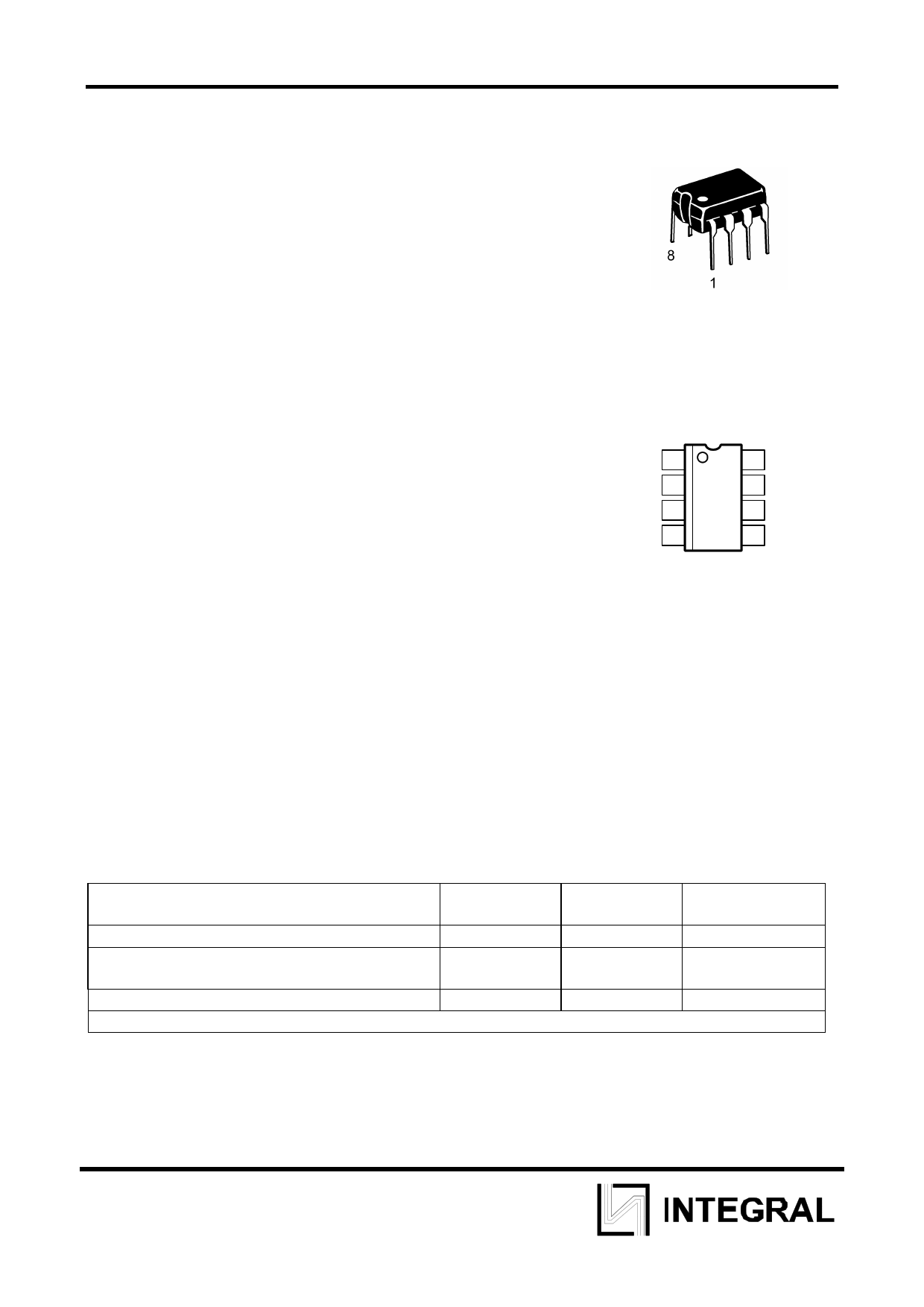
DIP-8 package of type
MS-001BA
TA=from -40oC to +110oC
Identification of Pins in the Package
UBatt 1
GND 2
UI 3
Osc 4
8 Output
7 2Us
6 Sense
5 Delay
Features:
Microcircuit is supplied from the car borne supply mains
Minimum number of the external time setting components.
Operating voltage range of the microcircuit supply from 9 V to 16,5 V.
Table of Limit Modes
Description of Parameter, Identification
Not less
Not more
Supply voltage UBatt
Storage temperature Tstg
32,5
-55 +125
Chip maximum temperature Tj(max)
+150
Temperature resistance chip - environment Rth j-a, =120 oC/Wt
Unit of
Measurement
V
oС
oС
1
1 page 
IL6083, IL6083-01
Functional Description
IC IL6083N is designed for direct control of power MOS transistor and is suitable for
control of lamps brightness for backlighting the indicator panel of the car borne systems
status. IC is connected directly to the transport vehicle mains (UBatt) via the resistor of 150
Оhm
(R4 in Figure 1), jointly with the decoupling filtering capacitor of 47 mcF (C1 in Figure 1).
The device has the internal oscillator, whose frequency depends upon capacitance of the
external capacitor С2.
Principle of operation of the pulse width modulation controller IC depends upon
porocity alteration of the positive voltage output pulses, arriving at the gate of the external
power MOS transistor in dependence upon voltage at the control input «UI» (pin 3)
(connection is done by means of the potentiometer).
Fill-up coefficient of the output signal is determined as ratio of the functioning pulse
duration to period and is within the range from 18 to 100% for IL6083N and from 10 to
100% for IL6083N-01.
If voltage increase occurs UBatt > 20 V (typ.), the external transistor is diabled and
enabled again at UBatt < 18,5 V (hysteresis).
If UBatt > 28,5 V (typ.), controller limits voltage, reducing it from Us = 26 V to 20 V.
In case of the high voltage occurance in the supply circuit, the gate of the external MOS
transistor remains under the microcircuit ground potential, thus performing voltage
separation between the transistor and the lamps (i. е. protects load). Meanwhile,
protection from short circuit does not function. At UBatt approximately < 23 V, the
overvoltage detection circuit of step 2 is diabled. Thus, during the overvoltage detection of
step 2 the lamp voltage Ulamp is computed by the formula:
Ulamp = UBatt - Us - Ugs
Us – microcircuit stabilized voltage during overvoltage detection of stage 2.
Ugs – voltage drain-gate at МОS transistor.
In case, when voltage (approximately) UBatt < 5V, the external MOS transistor is
disabled, and the detection circuit of short circuit is disabled. Hysteresis guarantees, that
the external MOS transistor will be enabled again at (approximately) UBatt > 5,4 V.
In order to protect the MOS transistor in case of the ground bus rupture it is
recommended to enable, to ensure the proper disabling, 1 МОhm resistor between gate
and supply.
Pulse wodth is controlled by means of the external potentiometer (47 kОhm),
connected to pin 3. Characteristic (turning angle / porosity) is linear. Fill-up coefficient of
the output pulse at pin 8 may also vary from 18 to 100 % for IL6083N and from 10 to 100%
for IL6083N-01. Further limitation of porosity is possible by means of the resistors R1 and
R3 (see Fig. 1).
In order to reduce the dissipated power at the external MOS transistor and extend
the service life of the lamps for backlighting the panel of indicators, the microcircuit
automatically reducing the maximum operating cycle at pin 8, if the stabilized voltage
exceeds Us = 13 V. Pin 3 is protected from short circuit relative to UBatt and ground (UBatt <
16,5 V).
Microcircuit internal RC oscillator determines the output voltage frequency at pin 8. It
is determined by the external capacitor С2. It is charged by means of direct current I, from
the first current source, until it attains the upper switching threshold voltage. Then the
second current source will be enabled, which will branch the double current I * 2 from the
charging current. Thus, capacitor С2 is discharged by means of the current I, until it
5
5 Page | ||
| Páginas | Total 7 Páginas | |
| PDF Descargar | [ Datasheet IL6083-01.PDF ] | |
Hoja de datos destacado
| Número de pieza | Descripción | Fabricantes |
| IL6083-01 | PULSE WIDTH MODULATION MICROCIRCUIT OF POWER MOS TRANSISTOR | Integral |
| Número de pieza | Descripción | Fabricantes |
| SLA6805M | High Voltage 3 phase Motor Driver IC. |
Sanken |
| SDC1742 | 12- and 14-Bit Hybrid Synchro / Resolver-to-Digital Converters. |
Analog Devices |
|
DataSheet.es es una pagina web que funciona como un repositorio de manuales o hoja de datos de muchos de los productos más populares, |
| DataSheet.es | 2020 | Privacy Policy | Contacto | Buscar |