|
|
|
PDF K50-HC Data sheet ( Hoja de datos )
| Número de pieza | K50-HC | |
| Descripción | Clock Crystal Oscillators Surface Mount Type | |
| Fabricantes | Kyocera | |
| Logotipo | ||
Hay una vista previa y un enlace de descarga de K50-HC (archivo pdf) en la parte inferior de esta página. Total 1 Páginas | ||
|
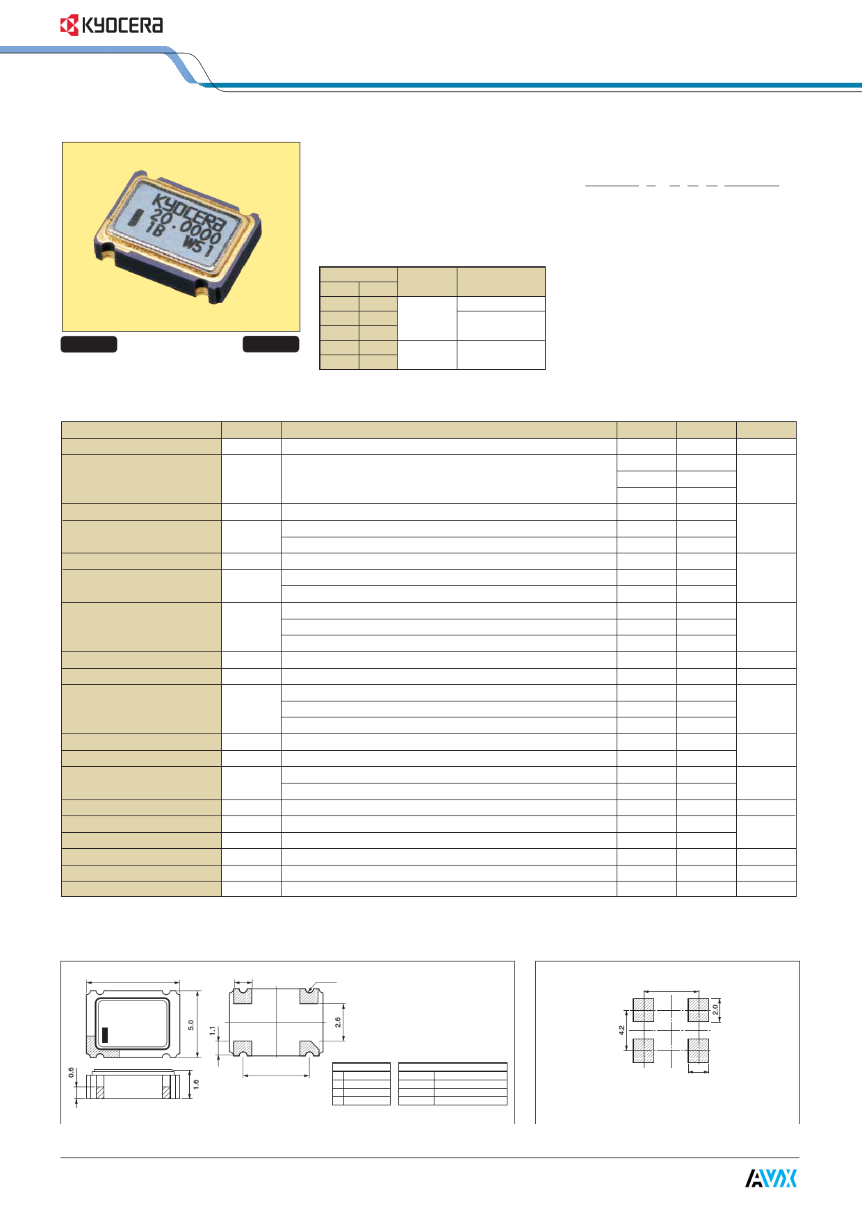
No Preview Available !
CMOS / 5.0V / 7.0×5.0A
Clock Crystal Oscillators
Surface Mount Type
K50-HC Series
Pb Free
RoHS Conforming
Features
• Miniature ceramic package
• Highly reliable with seam welding
• CMOS output
• Supply voltage VDD=5.0V
• ±25ppm available
Table 1
Stability
Code (ppm)
TOPR
(°C)
Note
0 ± 50
Standard specifications
S
± 30
−10 to +70
(Standard)
With
only
certain
U ± 25
frequencies
F ±100 −40 to +85 With only certain
G ± 50 (Extend) frequencies
How to Order
K50-HC 0 - C S E 25.0000
q w ert y
qType(7×5 SMD, 5.0V)
wFrequency Stability Code(See Table1)
eCMOS Output
rDuty Ratio(S: 45% to 55% STD)
tEnable/Disable Function(STD)
yOscillation Frequency(Ex.: 25.0000MHz)
Packaging(Tape & Reel 1Kpcs/reel)
Specifications
Item
Symbol
Conditions
Output Frequency Range
FOUT
Frequency Stability
FSBY
Overall conditions:
initial tolerance, operating temperature range, rated power
supply voltage change, load change, aging(1year @25°C),
shock and vibration
Storage Temperature Range TSTG
Operating Temperature Range TOPR
Standard
Extend(option)
Max. Supply Voltage
-----
Supply Voltage
Stability: ±50ppm, ±30ppm, ±100ppm(Ext Temp)
VDD Stability: ±25ppm, ±50ppm(Ext Temp)
Current Consumption
(Maximum Loaded)
1.5≤FOUT≤20MHz
IDD 20<FOUT≤40MHz
40<FOUT≤68MHz
Disable Current
IDE @68.0000MHz
Duty Ratio(Symmetry)
SYM @50% VDD
Rise/Fall Time
(10% VDD to 90% VDD Maximum Loaded)
Tr/Tf
8≤FOUT≤26MHz
26<FOUT≤45MHz
45<FOUT≤68MHz
Output Voltage-"L"
VOL IOL=16mA
Output Voltage-"H"
VOH IOH=−16mA
Output Load(CMOS)
Input Voltage Range
8≤FOUT≤50MHz
CL
50<FOUT≤68MHz
VIN
Input Voltage-"L"
VIL
Input Voltage-"H"
VIH
Output Disable Time
-----
Output Enable Time
-----
Start-up Time
ST @Minimum operating Voltage to be 0sec.
Note: Please contact us for inquires about extended operating temperature range, available frequencies and other conditions.
All electrical characteristics are defined at the maximum load and operating temperature range.
Min.
1.5
−25
−30
−50
−55
−10
−40
−0.5
4.5
4.75
-----
-----
-----
-----
45
-----
-----
-----
-----
90% VDD
-----
-----
0
-----
2.2
-----
-----
-----
Max.
68
+25
+30
+50
+125
+70
+85
7.0
5.5
5.25
25
35
50
30
55
10
8
5
10% VDD
-----
50
15
VDD
0.8
-----
100
100
10
Units
MHz
ppm
°C
Volt
mA
mA
%
nS
Volt
pF
Volt
Volt
nS
nS
mS
Dimensions
7.0
1.4
e
w
R0.35
r
q
(Unit : mm) Recommended Land Pattern (Unit : mm)
Plating: Ni+Au
Tolerance: ±0.2
5.08
5.08
Pin Connections
Enable/Disable Function
q Control
Pin1
Pin3(Output)
w Case GND
Open
Active
e Output
"H" Level
Active
r VDD
"L" Level
High Z
1.8
Note: A capacitor of value 0.01µF between VDD
and GND is recommended.
1 page | ||
| Páginas | Total 1 Páginas | |
| PDF Descargar | [ Datasheet K50-HC.PDF ] | |
Hoja de datos destacado
| Número de pieza | Descripción | Fabricantes |
| K50-HC | Clock Crystal Oscillators Surface Mount Type | Kyocera |
| Número de pieza | Descripción | Fabricantes |
| SLA6805M | High Voltage 3 phase Motor Driver IC. |
Sanken |
| SDC1742 | 12- and 14-Bit Hybrid Synchro / Resolver-to-Digital Converters. |
Analog Devices |
|
DataSheet.es es una pagina web que funciona como un repositorio de manuales o hoja de datos de muchos de los productos más populares, |
| DataSheet.es | 2020 | Privacy Policy | Contacto | Buscar |