|
|
|
PDF VN1160T Data sheet ( Hoja de datos )
| Número de pieza | VN1160T | |
| Descripción | DIRECTION INDICATOR DRIVER | |
| Fabricantes | STMicroelectronics | |
| Logotipo | ||
Hay una vista previa y un enlace de descarga de VN1160T (archivo pdf) en la parte inferior de esta página. Total 10 Páginas | ||
|
No Preview Available !
®
TYPE
VN1160
VN1160-1
VN1160T
RDS(on)
0.08 Ω
Ilim
12 A
VCC
40 V
s COMPLETE DIRECTION INDICATOR IN A 3
PIN PACKAGE
s REQUIRES ONLY ONE EXTERNAL
CAPACITOR TO SET FLASHING FREQUENCY
s DOUBLE FREQUENCY FLASHING IN LOW
LOAD CONDITIONS
s CYCLE BY CYCLE OVERTEMPERATURE
SHUTDOWN
s REVERSE BATTERY PROTECTION
DESCRIPTION
The VN1160, VN1160-1, VN1160T are a monolithic
device made by using STMicroelectronics VIPower
technology, intended for building a complete flashing unit
for two wheel vehicles. The device is connected between
the battery positive terminal (VCC pin) and a mechanical
switch to the right and/or left bulbs. As soon as the series
switch connects the OUT pin to the bulbs, the device
begins to turn on/off with a 50% duty cycle.
An external low voltage capacitor (220µF, 10V)
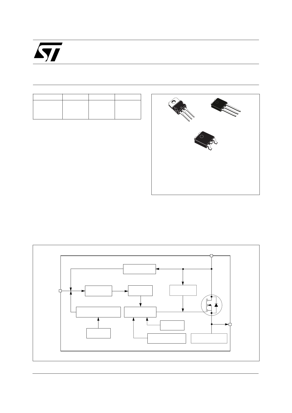
BLOCK DIAGRAM
VN1160/
VN1160-1/ VN1160T
DIRECTION INDICATOR
DRIVER FOR MOTORBIKE
TARGET SPECIFICATION
3
2
1
TO-220
3
2
1
TO251 (IPAK)
3
1
TO252 (DPAK)
ORDER CODES
TO-252 (DPAK)
TO-251 (IPAK)
TO-220
VN1160
VN1160-1
VN1160T
connected between the CEXT pin and the OUT pin
stores energy for powering the device during the ON
phase and sets the flashing frequency.
When a low load is detected (output current lower than
Idf), flashing frequency is automatically doubled.
VCC
CEXT CAPACITOR
CHARGING
CEXT
SAWTOOTH
GENERATOR
CONTROL
LOGIC
OVERVOLTAGE
CLAMP
FLASHING FREQUENCY POWER MOSFET
REGULATION
GATE DRIVER
LOW LOAD
DETECTION
CURRENT
LIMITER
OUT
JUNCTION
REVERSE BATTERY
OVERTEMPERATURE
PROTECTION
February 1999
1/10
1
1 page 
VN1160/ VN1160-1/ VN1160T
FUNCTIONAL DESCRIPTION
1) Normal operation (see Fig.1)
When a nominal load (higher than a 20W bulb) is
connected to the OUT pin, the device oscillates by
charging the CEXT capacitor up to the threshold voltage
Vch quickly, and then slowly discharging CEXT to the
threshold voltage Vcl by a constant current ICEXT.
The self oscillating frequency of the device is determined
by the relation :
fosc
=
-----------------------I---c---e---x----t-----------------------
2 × Cext × (Vch – Vcl)
The duty cycle is close to 50%.
2) Low load condition (see Fig.1)
If the load is lower than the load of a 14W bulb, the
device will detect the low load at the end of the ON
phase, and will double the oscillating frequency.
3) Overload and overtemperature shutdown (see
Fig.1)
In the case of a short circuit of the load, the output current
IOUT is limited to the ILIM value.
If the junction temperature becomes too hot (Tj > Tjsh),
the device turns off, and waits for the next cycle to turn on
providing that the junction temperature has cooled to
below Tjrs.
5/10
1
5 Page | ||
| Páginas | Total 10 Páginas | |
| PDF Descargar | [ Datasheet VN1160T.PDF ] | |
Hoja de datos destacado
| Número de pieza | Descripción | Fabricantes |
| VN1160 | DIRECTION INDICATOR DRIVER | STMicroelectronics |
| VN1160-1 | DIRECTION INDICATOR DRIVER | STMicroelectronics |
| VN1160T | DIRECTION INDICATOR DRIVER | STMicroelectronics |
| Número de pieza | Descripción | Fabricantes |
| SLA6805M | High Voltage 3 phase Motor Driver IC. |
Sanken |
| SDC1742 | 12- and 14-Bit Hybrid Synchro / Resolver-to-Digital Converters. |
Analog Devices |
|
DataSheet.es es una pagina web que funciona como un repositorio de manuales o hoja de datos de muchos de los productos más populares, |
| DataSheet.es | 2020 | Privacy Policy | Contacto | Buscar |