|
|
|
PDF IRF820L Data sheet ( Hoja de datos )
| Número de pieza | IRF820L | |
| Descripción | Power MOSFET ( Transistor ) | |
| Fabricantes | Vishay | |
| Logotipo | ||
Hay una vista previa y un enlace de descarga de IRF820L (archivo pdf) en la parte inferior de esta página. Total 8 Páginas | ||
|
No Preview Available !
www.vishay.com
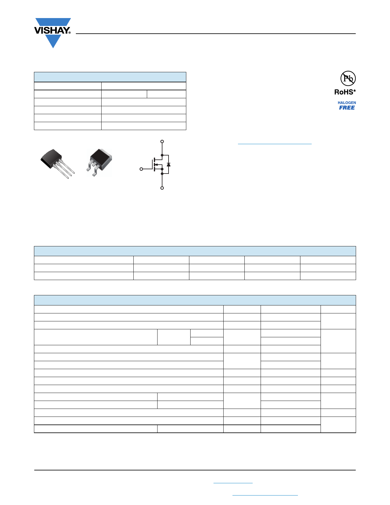
IRF820S, SiHF820S, IRF820L, SiHF820L
Vishay Siliconix
Power MOSFET
PRODUCT SUMMARY
VDS (V)
RDS(on) ()
Qg (Max.) (nC)
Qgs (nC)
Qgd (nC)
Configuration
500
VGS = 10 V
24
3.3
13
Single
I2PAK (TO-262)
D2PAK (TO-263)
3.0
D
G
DS
G
D
S
G
S
N-Channel MOSFET
FEATURES
• Surface mount
• Available in tape and reel
• Dynamic dV/dt rating
Available
• Repetitive avalanche rated
• Fast switching
Available
• Ease of paralleling
• Simple drive requirements
• Material categorization: for definitions of compliance
please see www.vishay.com/doc?99912
Note
* This datasheet provides information about parts that are
RoHS-compliant and / or parts that are non-RoHS-compliant. For
example, parts with lead (Pb) terminations are not RoHS-compliant.
Please see the information / tables in this datasheet for details.
DESCRIPTION
Third generation power MOSFETs from Vishay provide the
designer with the best combination of fast switching,
ruggedized device design, low on-resistance and
cost-effectiveness.
The D2PAK (TO-263) is a surface mount power package
capable of accommodating die size up to HEX-4. It provides
the highest power capability and the lowest possible
on-resistance in any existing surface mount package. The
D2PAK (TO-263) is suitable for high current applications
because of its low internal connection resistance and can
dissipate up to 2.0 W in a typical surface mount application.
ORDERING INFORMATION
Package
Lead (Pb)-free and halogen-free
Lead (Pb)-free
Note
a. See device orientation.
D2PAK (TO-263)
SiHF820S-GE3
IRF820SPbF
D2PAK (TO-263)
SiHF820STRL-GE3 a
IRF820STRLPbF a
D2PAK (TO-263)
SiHF820STRR-GE3 a
IRF820STRRPbF a
I2PAK (TO-262)
SiHF820L-GE3
IRF820LPbF
ABSOLUTE MAXIMUM RATINGS (TC = 25 °C, unless otherwise noted)
PARAMETER
SYMBOL
Drain-Source Voltage
Gate-Source Voltage
Continuous Drain Current
Pulsed Drain Current a
Linear Derating Factor
Linear Derating Factor (PCB mount) e
Single Pulse Avalanche Energy b
Avalanche Current a
Repetitive Avalanche Energy a
Maximum Power Dissipation
Maximum Power Dissipation (PCB mount) e
Peak Diode Recovery dV/dt c
VGS at 10 V
TC = 25 °C
TC = 100 °C
VDS
VGS
ID
IDM
TC = 25 °C
TA = 25 °C
EAS
IAR
EAR
PD
dV/dt
Operating Junction and Storage Temperature Range
Soldering Recommendations (Peak temperature) d
for 10 s
TJ, Tstg
Notes
a. Repetitive rating; pulse width limited by maximum junction temperature (see fig. 11).
b. VDD = 50 V, starting TJ = 25 °C, L = 60 mH, Rg = 25 , IAS = 2.5 A (see fig. 12).
c. ISD 2.5 A, dI/dt 50 A/μs, VDD VDS, TJ 150 °C.
d. 1.6 mm from case.
e. When mounted on 1" square PCB (FR-4 or G-10 material).
LIMIT
500
± 20
2.5
1.6
8.0
0.40
0.025
210
2.5
5.0
50
3.1
3.5
-55 to +150
300
UNIT
V
A
W/°C
mJ
A
mJ
W
V/ns
°C
S15-1659-Rev. D, 20-Jul-15
1
Document Number: 91060
For technical questions, contact: [email protected]
THIS DOCUMENT IS SUBJECT TO CHANGE WITHOUT NOTICE. THE PRODUCTS DESCRIBED HEREIN AND THIS DOCUMENT
ARE SUBJECT TO SPECIFIC DISCLAIMERS, SET FORTH AT www.vishay.com/doc?91000
1 page 
www.vishay.com
IRF820S, SiHF820S, IRF820L, SiHF820L
Vishay Siliconix
VDS
Vary tp to obtain
required IAS
Rg
10 V
tp
L
D.U.T
IAS
0.01 W
+
- V DD
Fig. 12a - Unclamped Inductive Test Circuit
VDS
VDS
tp
VDD
IAS
Fig. 12b - Unclamped Inductive Waveforms
500
ID
Top 1.1 A
400 1.6 A
Bottom 2.5 A
300
200
100
0 VDD = 50 V
25 50
75 100 125 150
91060_12c
Starting TJ, Junction Temperature (°C)
Fig. 12c - Maximum Avalanche Energy vs. Drain Current
10 V
QGS
VG
QG
QGD
Charge
Fig. 13a - Basic Gate Charge Waveform
Current regulator
Same type as D.U.T.
12 V
50 kΩ
0.2 µF
0.3 µF
+
D.U.T. - VDS
VGS
3 mA
IG ID
Current sampling resistors
Fig. 13b - Gate Charge Test Circuit
S15-1659-Rev. D, 20-Jul-15
5
Document Number: 91060
For technical questions, contact: [email protected]
THIS DOCUMENT IS SUBJECT TO CHANGE WITHOUT NOTICE. THE PRODUCTS DESCRIBED HEREIN AND THIS DOCUMENT
ARE SUBJECT TO SPECIFIC DISCLAIMERS, SET FORTH AT www.vishay.com/doc?91000
5 Page | ||
| Páginas | Total 8 Páginas | |
| PDF Descargar | [ Datasheet IRF820L.PDF ] | |
Hoja de datos destacado
| Número de pieza | Descripción | Fabricantes |
| IRF820 | N-Channel MOSFET Transistor | Inchange Semiconductor |
| IRF820 | N-CHANNEL Enhancement-Mode Silicon Gate TMOS | Motorola Inc |
| IRF820 | N - CHANNEL 500V - 2.5ohm - 2.5 A - TO-220 PowerMESH] MOSFET | STMicroelectronics |
| IRF820 | N-CHANNEL POWER MOSFETS | Samsung semiconductor |
| Número de pieza | Descripción | Fabricantes |
| SLA6805M | High Voltage 3 phase Motor Driver IC. |
Sanken |
| SDC1742 | 12- and 14-Bit Hybrid Synchro / Resolver-to-Digital Converters. |
Analog Devices |
|
DataSheet.es es una pagina web que funciona como un repositorio de manuales o hoja de datos de muchos de los productos más populares, |
| DataSheet.es | 2020 | Privacy Policy | Contacto | Buscar |