|
|
|
PDF LD7904JGP7 Data sheet ( Hoja de datos )
| Número de pieza | LD7904JGP7 | |
| Descripción | Green Mode Power Switch | |
| Fabricantes | Leadtrend Technology | |
| Logotipo | ||
Hay una vista previa y un enlace de descarga de LD7904JGP7 (archivo pdf) en la parte inferior de esta página. Total 16 Páginas | ||
|
No Preview Available !
LD7904JGP7
3/21/2012
Green Mode Power Switch
REV:00b
General Description
The LD7904JGP7 is a green mode PWM chip integrated
with a 700V MOSFET in a DIP-6 package. It’s operating at
fixed frequency of 100KHz. With multi-functions built-in this
IC , such as high voltage startup, OLP/OVP/OTP protection,
internal current mode slope compensation, and
green-mode power-saving operation under light load or no
load condition, this highly integrated device provides high
efficiency, low external component counts, and low cost
solution for compact power applications.
Features
Built-in 700V Power MOSFET
Built-in High Voltage startup circuit
Fixed Switching Frequency at 100KHz
Frequency Trembling for EMI improve
Internal High Voltage Startup Circuit
Under Voltage Lockout (UVLO) on VCC Pin
Current Mode Control with Slope Compensation
Green-Mode Control for Power Saving
OVP / OLP / Internal Thermal Shut Down
Applications
Switching AC/DC Adaptor
LCD TV or PC Standby Power
SMPS for LCD Monitor
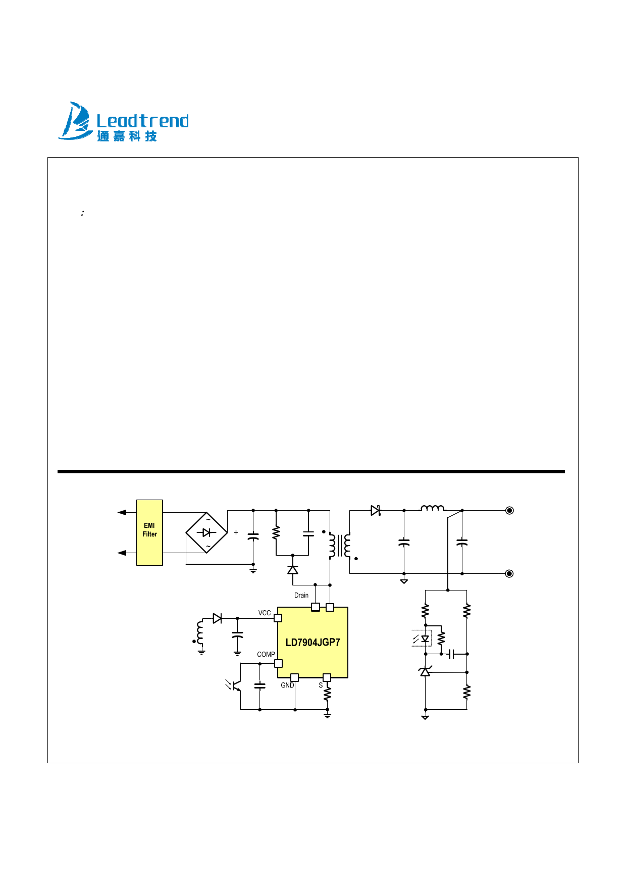
Typical Application
Leadtrend Technology Corporation
LD7904JGP7-DS-00b March 2012
1
www.leadtrend.com.tw
1 page 
LD7904JGP7
Absolute Maximum Ratings
Supply Voltage VCC
COMP
S pin DC Voltage
S pin negative pulse voltage (Duration Time < 100nS)
Drain
Peak Pulse drain current
Total Maximum Power Dissipation of (25C)
Package thermal resistance (DIP-6)
θJA
θJC
Operating Junction Temperature Range
Operating Ambient Temperature Range
Storage Temperature Range
Lead temperature (Soldering, 10sec)
ESD Voltage Protection, Human Body Model (Exclusive Drain Pin)
ESD Voltage Protection, Machine Model (Exclusive Drain Pin)
-0.3V~30V
-0.3V ~7V
-0.3V ~7V
-1.5V
-0.3V~700V
4A
1.25W
80C/W
30C/W
-40C to 125C
-20C to 85C
-65C to 150C
260C
2.5KV
250 V
Caution:
Stresses beyond the ratings specified in “Absolute Maximum Ratings” may cause permanent damage to the device. This is a stress only
rating and operation of the device at these or any other conditions above those indicated in the operational sections of this specification is not
implied.
Leadtrend Technology Corporation
LD7904JGP7-DS-00b March 2012
5
www.leadtrend.com.tw
5 Page 
LD7904JGP7
the RT/CT pin through a coupling capacitor. In the
LD7904JGP7, the internal slope compensation circuit has
been implemented to simplify the external circuit design.
On/Off Control
The gate driver of LD7904JGP7 can be disabled
immediately by pulling COMP pin voltage level lower than
Zero Duty Trip Level. The disable-mode can be released
when Comp pin voltage level higher than Zero Duty Trip
Level.
Fig. 14
Current Sensing and Leading-edge Blanking
The typical current mode of PWM controller feedbacks both
current signal and voltage signal to close the control loop
and achieve regulation. The LD7904JGP7 detects the
internal MOSFET current from the S pin and pulse-by-pulse
limt current. The maximum voltage threshold of the current
sensing pin is Vcs_off (~0.45V). The MOSFET peak current
can be obtain from below equation.
IPEAK(MAX)
Vcs _ off
RS
Due to integrated leading edge blanking circuit and internal
spike filter, it doesn’t need external LC filter parts.
Internal Slope Compensation
Stability is crucial for current mode control when it operates
at CCM and more than 50% of duty-cycle. To stabilize the
control loop, the slope compensation is required in the
traditional UC384X design by injecting the ramp signal from
Oscillator and Switching Frequency
The switching frequency of LD7904JGP7 is fixed at 100KHz
to provide the optimized operations by considering the EMI
performance, thermal treatment, component sizes and
transformer design. The Trembling frequency is internally
pre-set for 6.2KHz when incorporating with 100KHz
switching frequency.
Green-Mode Operation
By using the green-mode control, the switching frequency
can be reduced under the light load condition. This feature
helps to improve the efficiency in light load conditions. The
green-mode control is Leadtrend Technology’s own IP.
Maximum Duty-Cycle
The maximum duty-cycle of LD7904JGP7 is limited to 75%
to avoid the transformer saturation.
Voltage Feedback Loop
The voltage feedback signal is provided from the TL431 in
the secondary side through the photo-coupler to the COMP
pin of LD7904JGP7. The input stage of LD7904JGP7, like
the UC384X, is incorporated with 2 diodes voltage offset
circuit and a voltage divider with 1/6 ratio. Therefore,
V(PWMCOMPARATOR )
1
6
(VCOMP
2VF )
11
Leadtrend Technology Corporation www.leadtrend.com.tw
LD7904JGP7-DS-00b March 2012
11 Page | ||
| Páginas | Total 16 Páginas | |
| PDF Descargar | [ Datasheet LD7904JGP7.PDF ] | |
Hoja de datos destacado
| Número de pieza | Descripción | Fabricantes |
| LD7904JGP7 | Green Mode Power Switch | Leadtrend Technology |
| LD7904JGPN | Green Mode Power Switch | Leadtrend Technology |
| Número de pieza | Descripción | Fabricantes |
| SLA6805M | High Voltage 3 phase Motor Driver IC. |
Sanken |
| SDC1742 | 12- and 14-Bit Hybrid Synchro / Resolver-to-Digital Converters. |
Analog Devices |
|
DataSheet.es es una pagina web que funciona como un repositorio de manuales o hoja de datos de muchos de los productos más populares, |
| DataSheet.es | 2020 | Privacy Policy | Contacto | Buscar |