|
|
|
PDF IRFS4127PbF Data sheet ( Hoja de datos )
| Número de pieza | IRFS4127PbF | |
| Descripción | Power MOSFET ( Transistor ) | |
| Fabricantes | International Rectifier | |
| Logotipo | ||
Hay una vista previa y un enlace de descarga de IRFS4127PbF (archivo pdf) en la parte inferior de esta página. Total 10 Páginas | ||
|
No Preview Available !
Applications
l High Efficiency Synchronous Rectification in SMPS
l Uninterruptible Power Supply
l High Speed Power Switching
l Hard Switched and High Frequency Circuits
G
Benefits
l Improved Gate, Avalanche and Dynamic dV/dt
Ruggedness
l Fully Characterized Capacitance and Avalanche
SOA
l Enhanced body diode dV/dt and dI/dt Capability
l Lead-Free
PD - 96177
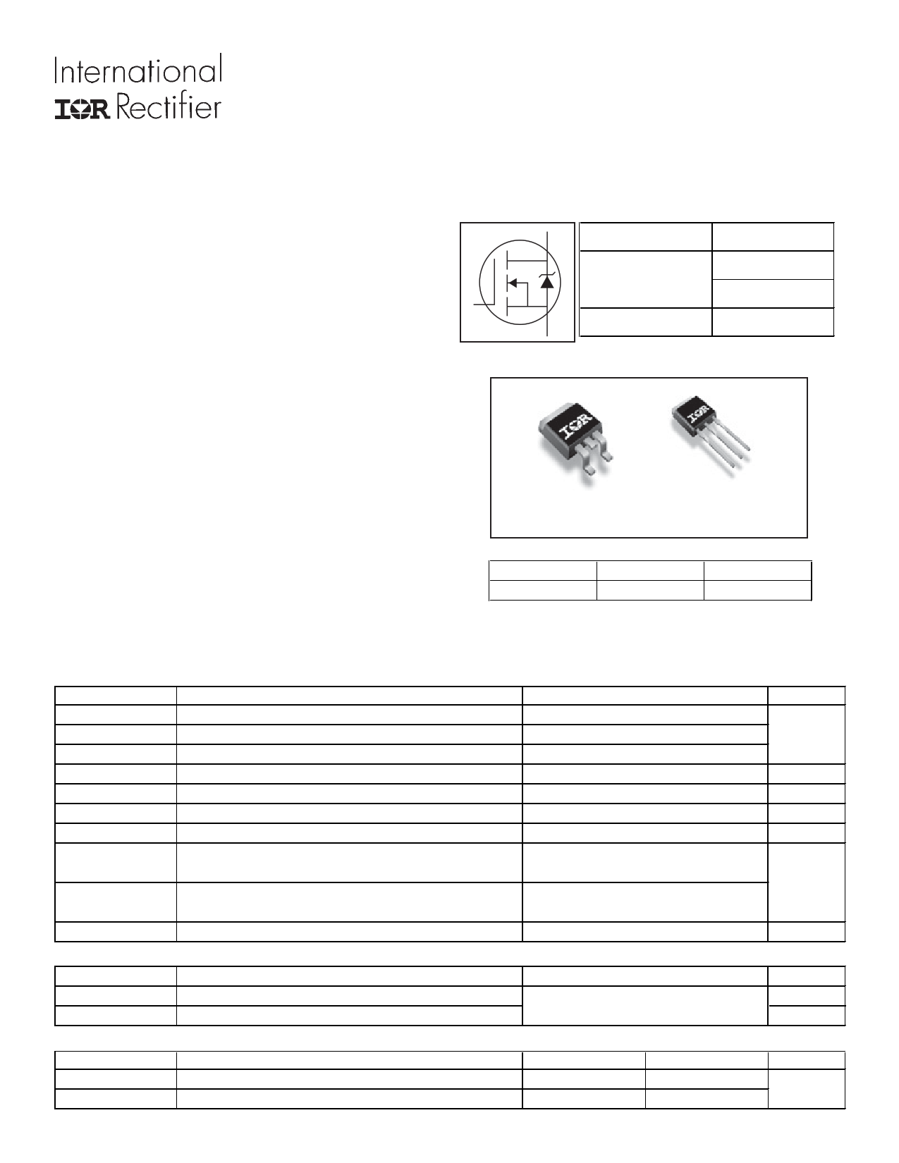
IRFS4127PbF
IRFSL4127PbF
HEXFET® Power MOSFET
D VDSS
200V
:RDS(on) typ. 18.6m
max. 22m:
S ID
72A
DD
S
G
D2Pak
IRFS4127PbF
S
D
G
TO-262
IRFSL4127PbF
G
Gate
D
Drain
S
Source
Absolute Maximum Ratings
Symbol
Parameter
ID @ TC = 25°C
Continuous Drain Current, VGS @ 10V
ID @ TC = 100°C
IDM
Continuous Drain Current, VGS @ 10V
cPulsed Drain Current
PD @TC = 25°C Maximum Power Dissipation
Linear Derating Factor
VGS
dv/dt
Gate-to-Source Voltage
ePeak Diode Recovery
TJ Operating Junction and
TSTG
Storage Temperature Range
Soldering Temperature, for 10 seconds
(1.6mm from case)
Mounting torque, 6-32 or M3 screw
Avalanche Characteristics
EAS (Thermally limited)
IAR
EAR
dSingle Pulse Avalanche Energy
cAvalanche Current
fRepetitive Avalanche Energy
Thermal Resistance
Symbol
RθJC
RθJA
Parameter
jkJunction-to-Case
ijJunction-to-Ambient
www.irf.com
Max.
72
51
300
375
2.5
± 20
57
-55 to + 175
300
x x10lb in (1.1N m)
250
See Fig. 14, 15, 22a, 22b,
Typ.
–––
–––
Max.
0.4
40
Units
A
W
W/°C
V
V/ns
°C
mJ
A
mJ
Units
°C/W
1
09/16/08
1 page 
IRFS/SL4127PbF
1
D = 0.50
0.1
0.20
0.10
0.05
0.01 0.02
0.01
0.001
1E-006
SINGLE PULSE
( THERMAL RESPONSE )
1E-005
0.0001
τJ
τJ
τ1
τ1
R1R1
CiC=iτi/Ri/iRi
R2R2
τ2 τ2
R3R3
R4R4
τC
Ri (°C/W)
0.02
τι (sec)
0.000019
τ3 τ4 τ 0.083333 0.000078
τ3 τ4 0.181667 0.001716
0.113333 0.008764
Notes:
1. Duty Factor D = t1/t2
2. Peak Tj = P dm x Zthjc + Tc
0.001
0.01
0.1
t1 , Rectangular Pulse Duration (sec)
Fig 13. Maximum Effective Transient Thermal Impedance, Junction-to-Case
100
Duty Cycle = Single Pulse
0.01
10 0.05
0.10
Allowed avalanche Current vs avalanche
pulsewidth, tav, assuming ∆Tj = 150°C and
Tstart =25°C (Single Pulse)
1 Allowed avalanche Current vs avalanche
pulsewidth, tav, assuming ∆Τ j = 25°C and
Tstart = 150°C.
0.1
1.0E-06
1.0E-05
1.0E-04
1.0E-03
tav (sec)
Fig 14. Typical Avalanche Current vs.Pulsewidth
1.0E-02
1.0E-01
250
TOP
Single Pulse
BOTTOM 1% Duty Cycle
200 ID = 44A
150
100
50
0
25
50 75 100 125 150 175
Starting TJ , Junction Temperature (°C)
Notes on Repetitive Avalanche Curves , Figures 14, 15:
(For further info, see AN-1005 at www.irf.com)
1. Avalanche failures assumption:
Purely a thermal phenomenon and failure occurs at a temperature far in
excess of Tjmax. This is validated for every part type.
2. Safe operation in Avalanche is allowed as long asTjmax is not exceeded.
3. Equation below based on circuit and waveforms shown in Figures 16a, 16b.
4. PD (ave) = Average power dissipation per single avalanche pulse.
5. BV = Rated breakdown voltage (1.3 factor accounts for voltage increase
during avalanche).
6. Iav = Allowable avalanche current.
7. ∆T = Allowable rise in junction temperature, not to exceed Tjmax (assumed as
25°C in Figure 14, 15).
tav = Average time in avalanche.
D = Duty cycle in avalanche = tav ·f
ZthJC(D, tav) = Transient thermal resistance, see Figures 13)
PD (ave) = 1/2 ( 1.3·BV·Iav) = DT/ ZthJC
Iav = 2DT/ [1.3·BV·Zth]
EAS (AR) = PD (ave)·tav
Fig 15. Maximum Avalanche Energy vs. Temperature
www.irf.com
5
5 Page | ||
| Páginas | Total 10 Páginas | |
| PDF Descargar | [ Datasheet IRFS4127PbF.PDF ] | |
Hoja de datos destacado
| Número de pieza | Descripción | Fabricantes |
| IRFS4127PbF | Power MOSFET ( Transistor ) | International Rectifier |
| Número de pieza | Descripción | Fabricantes |
| SLA6805M | High Voltage 3 phase Motor Driver IC. |
Sanken |
| SDC1742 | 12- and 14-Bit Hybrid Synchro / Resolver-to-Digital Converters. |
Analog Devices |
|
DataSheet.es es una pagina web que funciona como un repositorio de manuales o hoja de datos de muchos de los productos más populares, |
| DataSheet.es | 2020 | Privacy Policy | Contacto | Buscar |