|
|
|
PDF GB25RF120K Data sheet ( Hoja de datos )
| Número de pieza | GB25RF120K | |
| Descripción | IGBT PIM MODULE | |
| Fabricantes | International Rectifier | |
| Logotipo | ||
Hay una vista previa y un enlace de descarga de GB25RF120K (archivo pdf) en la parte inferior de esta página. Total 13 Páginas | ||
|
No Preview Available !
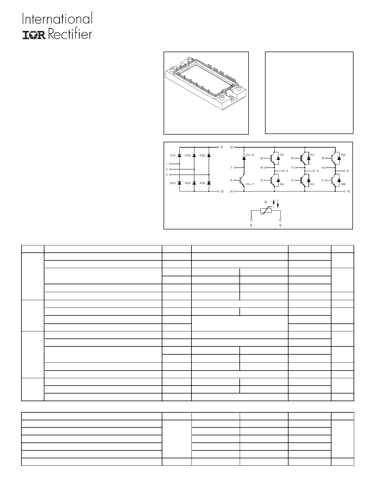
IGBT PIM MODULE
Features
• Low VCE (on) Non Punch Through IGBT Technology
• Low Diode VF
• 10µs Short Circuit Capability
• Square RBSOA
• HEXFRED Antiparallel Diode with Ultrasoft Diode
Reverse Recovery Characteristics
• Positive VCE (on) Temperature Coefficient
• Ceramic DBC Substrate
• Low Stray Inductance Design
Benefits
• Benchmark Efficiency for Motor Control
• Rugged Transient Performance
• Low EMI, Requires Less Snubbing
• Direct Mounting to Heatsink
• PCB Solderable Terminals
• Low Junction to Case Thermal Resistance
• UL Listed
ECONO2 PIM
PD - 94552
GB25RF120K
VCES = 1200V
IC = 25A, TC=80°C
tsc > 10µs, TJ=150°C
VCE(on) typ. = 2.40V
Absolute Maximum Ratings (TJ =25°C, unless otherwise indicated)
Parameter
Symbol Test Conditions
Inverter
Collector-to-Emitter Voltage
Gate-to-Emitter Voltage
Collector Current
Diode Maximum Forward Current
Power Dissipation
Input Repetitive Peak Reverse Voltage
Rectifier Average Output Current
Surge Current (Non Repetitive)
I2t (Non Repetitive)
Brake Collector-to-Emitter Voltage
Gate-to-Emitter Voltage
Collector Current
Power Dissipation
Repetitive Peak Reverse Voltage
Maximum Operating Junction Temperature
Storage Temperature Range
Isolation Voltage
VCES
VGES
IC
ICM
IFM d
PD
VRRM
IF(AV)
IFSM
I2t
VCES
VGES
IC
ICM
PD
VRRM
TJ
TSTG
VISOL
Continuous
1 device
25°C / 80°C
25°C
25°C
25°C
50/60Hz sine pulse
80°C
Rated VRRM applied, 10ms,
sine pulse
Continuous
1 device
25°C / 80°C
25°C
25°C
——
——
AC(1min.)
Thermal and Mechanical Characteristics
Parameter
Junction-to-Case Inverter IGBT Thermal Resistance
Junction-to-Case Inverter FRED Thermal Resistance
Junction-to-Case Brake IGBT Thermal Resistance
Junction-to-Case Brake Diode Thermal Resistance
Junction-to-Case Input Rectifier Thermal Resistance
Mounting Torque (M5)
Symbol
RTHJC
Min
—
—
—
—
—
2.7
Typical
—
—
—
—
—
—
1
Ratings
1200
±20
40 / 25
80
80
198
1600
20
250
316
1200
±20
25 / 15
50
104
1200
150
-40 to +125
2500
Units
V
A
W
V
A
A2s
V
A
W
V
°C
V
Maximum
0.63
1.0
1.2
2.3
0.85
3.3
Units
°C/W
Nm
www.irf.com
10/17/02
1 page 
16
14
12
10
8
6
4
2
0
0
400V
600V
50 100 150
Q G, Total Gate Charge (nC)
200
Inverter
100
90
80
70
60
50
40
30
20
10
0
0.0
GB25RF120K
25°C
125°C
1.0 2.0 3.0
VF (V)
4.0
Fig. 7 - Typical Gate Charge vs. VGE
ICE = 25A; L = 1mH
Fig. 8 - Typ. Diode Forward Characteristics
tp = 80µs
10000
9000
8000
7000
6000
5000
EON
4000
3000
2000
EOFF
1000
0
0 10 20 30 40 50 60
IC (A)
Fig. 9 - Typ. Energy Loss vs. IC
TJ = 125°C; L=400µH; VCE= 600V,RG= 10Ω; VGE= 15V
1000
tdOFF
tF
100 tdON
tR
10
0
10 20 30 40 50 60
IC (A)
Fig. 10 - Typ. Switching Time vs. IC
TJ = 125°C; L = 400µH; VCE = 600V,RG = 10Ω;VGE = 15V
6000
10000
5000
4000
3000
2000
EON
EOFF
1000 tdOFF
tF
tdON
100
1000
0
0 10 20 30 40 50
RG (Ω)
Fig. 11 - Typ. Energy Loss vs. RG
TJ = 125°C; L=400µH; VCE= 600V, ICE= 25A; VGE= 15V
www.irf.com
tR
10
0
10 20 30 40 50
RG (Ω)
Fig. 12 - Typ. Switching Time vs. RG
TJ = 125°C; L=400µH; VCE= 600V, ICE= 25A; VGE= 15V
5
5 Page 
Brake GB25RF120K
10
1
D = 0.50
0.20
0.1 0.10
0.05
0.02
0.01
0.01
0.001
SINGLE PULSE
( THERMAL RESPONSE )
τJ τJ
τ1 τ1
R1R1
Ci= τi/Ri
Ci i/Ri
R2R2
τ2 τ2
R3R3 Ri (°C/W)
τCτ 0.268
τ3τ3 0.642
0.290
τi (sec)
0.000469
0.018501
0.056904
Notes:
1. Duty Factor D = t1/t2
2. Peak Tj = P dm x Zthjc + Tc
0.0001
1E-006
1E-005
0.0001
0.001
0.01
0.1
t1 , Rectangular Pulse Duration (sec)
Fig 35. Maximum Transient Thermal Impedance, Junction-to-Case (Brake IGBT)
1
10
1 D = 0.50
0.20
0.10
0.1 0.05
0.02
0.01
0.01
SINGLE PULSE
( THERMAL RESPONSE )
τJ τJ
τ1 τ1
R1R1
Ci= τi/Ri
Ci i/Ri
R2R2
τ2 τ2
R3R3 Ri (°C/W) τi (sec)
τCτ 0.714 0.000489
τ3τ3 1.193 0.020644
0.394 0.154110
Notes:
1. Duty Factor D = t1/t2
2. Peak Tj = P dm x Zthjc + Tc
0.001
1E-006
1E-005
0.0001
0.001
0.01
0.1
t1 , Rectangular Pulse Duration (sec)
Fig 36. Maximum Transient Thermal Impedance, Junction-to-Case (Brake Diode)
1
900
45 900
45
800 40
tf
700 35
800
tr
700
40
35
600
90% ICE
30
500 25
600 TEST CURRENT 30
500 25
400 20 400 90% test current 20
300 5% VCE 15
200
5% ICE
10
100 5
0
Eof f Loss
0
300 15
10% test current
200
5% V CE
10
100 5
0 Eon Loss
0
-100
-0.60 -0.10
0.40 0.90
Time(µs)
1.40
-5
-100
-5
9.80 10.00 10.20 10.40 10.60 10.80
Time (µs)
Fig. WF3- Typ. Turn-off Loss Waveform
@ TJ = 125°C using Fig. CT.4
Fig. WF4- Typ. Turn-on Loss Waveform
@ TJ = 125°C using Fig. CT.4
www.irf.com
11
11 Page | ||
| Páginas | Total 13 Páginas | |
| PDF Descargar | [ Datasheet GB25RF120K.PDF ] | |
Hoja de datos destacado
| Número de pieza | Descripción | Fabricantes |
| GB25RF120K | IGBT PIM MODULE | International Rectifier |
| Número de pieza | Descripción | Fabricantes |
| SLA6805M | High Voltage 3 phase Motor Driver IC. |
Sanken |
| SDC1742 | 12- and 14-Bit Hybrid Synchro / Resolver-to-Digital Converters. |
Analog Devices |
|
DataSheet.es es una pagina web que funciona como un repositorio de manuales o hoja de datos de muchos de los productos más populares, |
| DataSheet.es | 2020 | Privacy Policy | Contacto | Buscar |