|
|
|
PDF EM3502 Data sheet ( Hoja de datos )
| Número de pieza | EM3502 | |
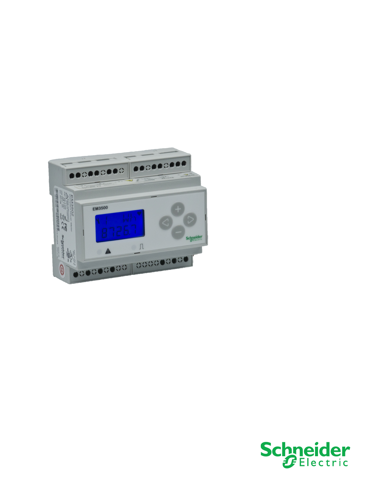
| Descripción | Compact Power and Energy Meter Manual | |
| Fabricantes | Schneider | |
| Logotipo | ||
Hay una vista previa y un enlace de descarga de EM3502 (archivo pdf) en la parte inferior de esta página. Total 30 Páginas | ||
|
No Preview Available !
EM3502, EM3550
Compact Power and Energy Meter
Installation Guide
ZL0092-0A
11/2011
1 page 
ZL0092-0A
11/2011
EM3502, 3550
Safety Precautions
SAFETY PRECAUTIONS
DANGER
HAZARD OF ELECTRIC SHOCK, EXPLOSION, OR ARC FLASH
• Follow safe electrical work practices. See NFPA 70E in the USA or
applicable local codes.
• This equipment must only be installed and serviced by qualified
electrical personnel.
• Read, understand, and follow the instructions before installing this
product.
• Turn off all power supplying equipment before working on or inside
the equipment.
• Always use a properly rated voltage sensing device to confirm power is
off.
• DO NOT DEPEND ON THIS PRODUCT FOR VOLTAGE INDICATION.
• Only install this product on insulated conductors.
• Install device in an appropriate electrical and fire enclosure per local
regulations.
• ESD sensitive equipment. Ground yourself and discharge any static
charge before handling this device.
• Any covers that may be displaced during the installation must be
reinstalled before powering the unit.
• Do not install on the load side of a Variable Frequency Drive (VFD), aka
Variable Speed Drive (VSD) or Adjustable Frequency Drive (AFD).
Failure to follow these instructions will result in death or serious injury.
INSTALLATION OVERVIEW
The meter can be mounted in two ways: on standard 35 mm DIN rail or
screw-mounted to the interior surface of the enclosure.
A. DIN Rail Mounting
1. Disconnect and lock out power. Use a properly rated voltage sensing device
to confirm power is off.
2. Attach mounting clips to the underside of the housing by sliding them into
the slots from the inside. The stopping pegs must face the housing, and the
outside edge of the clip must be flush with the outside edge of the housing.
3. Snap the clips onto the DIN rail.
4. To prevent horizontal shifting across the DIN rail, use two end stop clips.
B. Screw Mounting
1. Disconnect and lock out power. Use a properly rated voltage sensing device
to confirm power is off.
2. Attach the mounting clips to the underside of the housing by sliding them
into the slots from the outside. The stopping pegs must face the housing,
and the screw hole must be exposed on the outside of the housing.
3. Use three #8 screws (not supplied) to mount the meter to the inside of the
enclosure.
NOTE: For detailed instructions, please see the “Installation” section
later in this guide.
© 2011 Schneider Electric All Rights Reserved.
1
5 Page 
ZL0092-0A
11/2011
INSTALLATION
A. DIN Rail Mounting
B. Screw Mounting
EM3502, 3550
Installation
The meter can be mounted in two ways: on standard 35 mm DIN rail or
screw-mounted to the interior surface of the enclosure.
1. Disconnect and lock out power. Use a properly rated voltage sensing device
to confirm power is off.
2. Attach mounting clips to the underside of the housing by sliding them into
the slots from the inside. The stopping pegs must face the housing, and the
outside edge of the clip must be flush with the outside edge of the housing.
3. Snap the clips onto the DIN rail. See diagram of the underside of the
housing (Figure 3).
Figure 3 Attach mounting clips for DIN rail
Insert clips from
inside
Clip flush
with outside
edge
Snap onto
DIN rail
4. To prevent horizontal shifting across the DIN rail, use two end stop clips.
1. Disconnect and lock out power. Use a properly rated voltage sensing device
to confirm power is off.
2. Attach the mounting clips to the underside of the housing by sliding them
into the slots from the outside. The stopping pegs must face the housing,
and the screw hole must be exposed on the outside of the housing.
3. Use three #8 screws (not supplied) to mount the meter to the inside of the
enclosure. See diagram of the underside of the housing (Figure 4).
Figure 4 Attach clips for screw mounting
Insert clips from
outside
Screw
holes
exposed
for
mounting
© 2011 Schneider Electric All Rights Reserved.
7
11 Page | ||
| Páginas | Total 30 Páginas | |
| PDF Descargar | [ Datasheet EM3502.PDF ] | |
Hoja de datos destacado
| Número de pieza | Descripción | Fabricantes |
| EM3502 | Compact Power and Energy Meter Manual | Schneider |
| EM3503 | Euro-Mag Terminal Blocks | Cooper Bussmann |
| Número de pieza | Descripción | Fabricantes |
| SLA6805M | High Voltage 3 phase Motor Driver IC. |
Sanken |
| SDC1742 | 12- and 14-Bit Hybrid Synchro / Resolver-to-Digital Converters. |
Analog Devices |
|
DataSheet.es es una pagina web que funciona como un repositorio de manuales o hoja de datos de muchos de los productos más populares, |
| DataSheet.es | 2020 | Privacy Policy | Contacto | Buscar |