|
|
|
PDF FTU220 Data sheet ( Hoja de datos )
| Número de pieza | FTU220 | |
| Descripción | N-Channel MOSFET | |
| Fabricantes | IPS | |
| Logotipo | ||
Hay una vista previa y un enlace de descarga de FTU220 (archivo pdf) en la parte inferior de esta página. Total 9 Páginas | ||
|
No Preview Available !
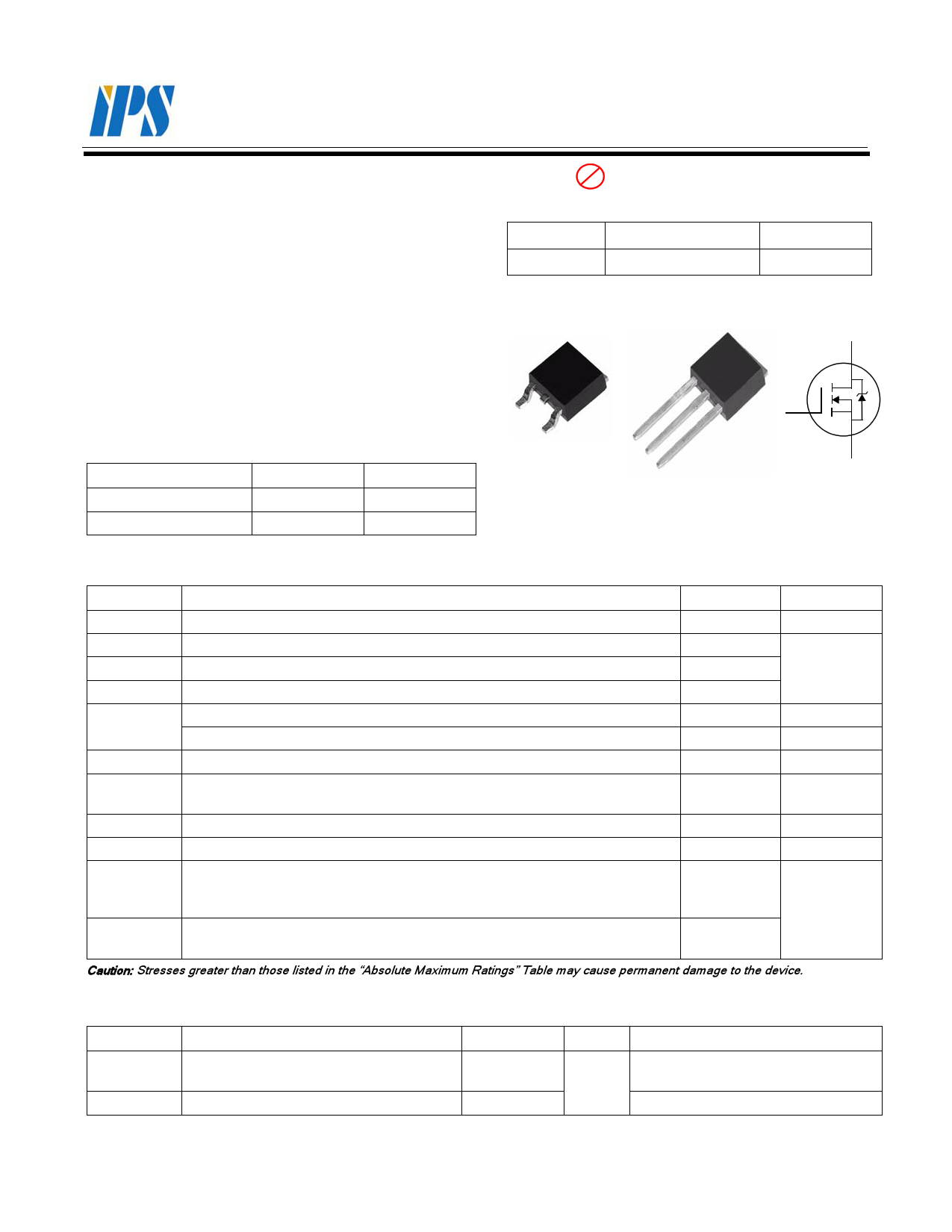
FTD220
FTU220
N-Channel MOSFET
Applications:
• CRT / TV Monitor
• Telecom
• Datacom
Features:
• RoHS Compliant
• Low ON Resistance
• Low Gate Charge
• Peak Current vs Pulse Width Curve
• Inductive Switching Curves
Ordering Information
PART NUMBER
FTD220
FTU220
PACKAGE
TO-252
TO-251
BRAND
FTD220
FTU220
Pb Lead Free Package and Finish
VDSS
200V
RDS(ON) (Max.)
0.60 Ω
ID
6.0A
D
G
S TO-252
G
D
S
Packages
Not to Scale
G
TO-251
D
S
Absolute Maximum Ratings TC=25 oC unless otherwise specified
Symbol
Parameter
Maximum
Units
VDSS
ID
ID@ 100 oC
IDM
PD
VGS
EAS
IAS
dv/dt
Drain-to-Source Voltage
Continuous Drain Current
Continuous Drain Current
Pulsed Drain Current, VGS@ 10V
Power Dissipation
Derating Factor above 25 oC
Gate-to-Source Voltage
Single Pulse Avalanche Engergy
L=10 mH, ID=3.9 Amps
Pulsed Avalanche Rating
Peak Diode Recovery dv/dt
(NOTE *1)
(NOTE *2)
(NOTE *3)
200
6.0
Figure 3
Figure 6
48
0.38
± 30
75
Figure 8
3.0
V
A
W
W/ oC
V
mJ
V/ ns
TL
TPKG
TJ and TSTG
Maximum Temperature for Soldering
Leads at 0.063in (1.6mm) from Case for 10 seconds
Package Body for 10 seconds
Operating Junction and Storage
Temperature Range
300
260
-55 to 150
oC
Caution: Stresses greater than those listed in the “Absolute Maximum Ratings” Table may cause permanent damage to the device.
Thermal Resistance
Symbol
Parameter
RθJC
RθJA
Junction-to-Case
Junction-to-Ambient
©2007 InPower Semiconductor Co., Ltd.
Maximum
2.5
100
Units
oC/W
Test Conditions
Water cooled heatsink, PD adjusted for
a peak junction temperature of +150 oC.
1 cubic foot chamber, free air.
FTD220 / FTU220 REV. A. May 2007
1 page 
Figure 6. Maximum Peak Current Capability
100 TRANSCONDUCTANCE
MAY LIMIT CURRENT IN
THIS REGION
10
1
VGS = 10V
0
10E-6
1E-6
100E-6
1E-3
10E-3
tp, Pulse Width (s)
100E-3
FOR TEMPERATURES
ABOVE 25oC DERATE PEAK
CURRENT AS FOLLOWS:
I = I25
1---5----0----–----T----C---
125
1E+0
10E+0
Figure 7. Typical Transfer Characteristics
10
PULSE DURATION = 10 µs
DUTY CYCLE = 0.5% MAX
8 VDS = 10 V
6
4
2
0
3.0
+150 oC
+25 oC
-55 oC
4.0 5.0 6.0 7.0 8.0
VGS, Gate-to-Source Voltage (V)
9.0
Figure8. Unclamped Inductive
Switching Capability
100
10.0
STARTING TJ = 25 oC
STARTING TJ = 150 oC
1.0
If R= 0: tAV= (L×IAS)/(1.3BVDSS-VDD)
If R≠ 0: tAV= (L/R) ln[IAS×R)/(1.3BVDSS-VDD)+1]
R equals total Series resistance of Drain circuit
0.1
1E-6
10E-6
100E-6
1E-3
tAV, Time in Avalanche (s)
10E-3
Figure 9. Typical Drain-to-Source ON
Resistance vs Drain Current
2.0
PULSE DURATION = 2 µs
DUTY CYCLE = 0.5% MAX
TC=25°C
1.5
1.0 VGS = 10V
0.5
0.0
0
VGS = 20V
5 10 15
ID, Drain Current (A)
20
©2007 InPower Semiconductor Co., Ltd.
Figure 10. Typical Drain-to-Source ON Resistance
vs Junction Temperature
2.50
2.25
2.00
1.75
1.50
1.25
1.00
0.75
0.50
PULSE DURATION = 10 µs
DUTY CYCLE = 0.5% MAX
0.25
VGS = 10V, ID = 6.0A
-75 -50 -25 0 25 50 75 100 125 150
TJ, Junction Temperature (oC)
FTD220 / FTU220 REV. A . May 2007
Page 5 of 9
5 Page | ||
| Páginas | Total 9 Páginas | |
| PDF Descargar | [ Datasheet FTU220.PDF ] | |
Hoja de datos destacado
| Número de pieza | Descripción | Fabricantes |
| FTU220 | N-Channel MOSFET | IPS |
| Número de pieza | Descripción | Fabricantes |
| SLA6805M | High Voltage 3 phase Motor Driver IC. |
Sanken |
| SDC1742 | 12- and 14-Bit Hybrid Synchro / Resolver-to-Digital Converters. |
Analog Devices |
|
DataSheet.es es una pagina web que funciona como un repositorio de manuales o hoja de datos de muchos de los productos más populares, |
| DataSheet.es | 2020 | Privacy Policy | Contacto | Buscar |