|
|
|
PDF VS-UFB310CB40 Data sheet ( Hoja de datos )
| Número de pieza | VS-UFB310CB40 | |
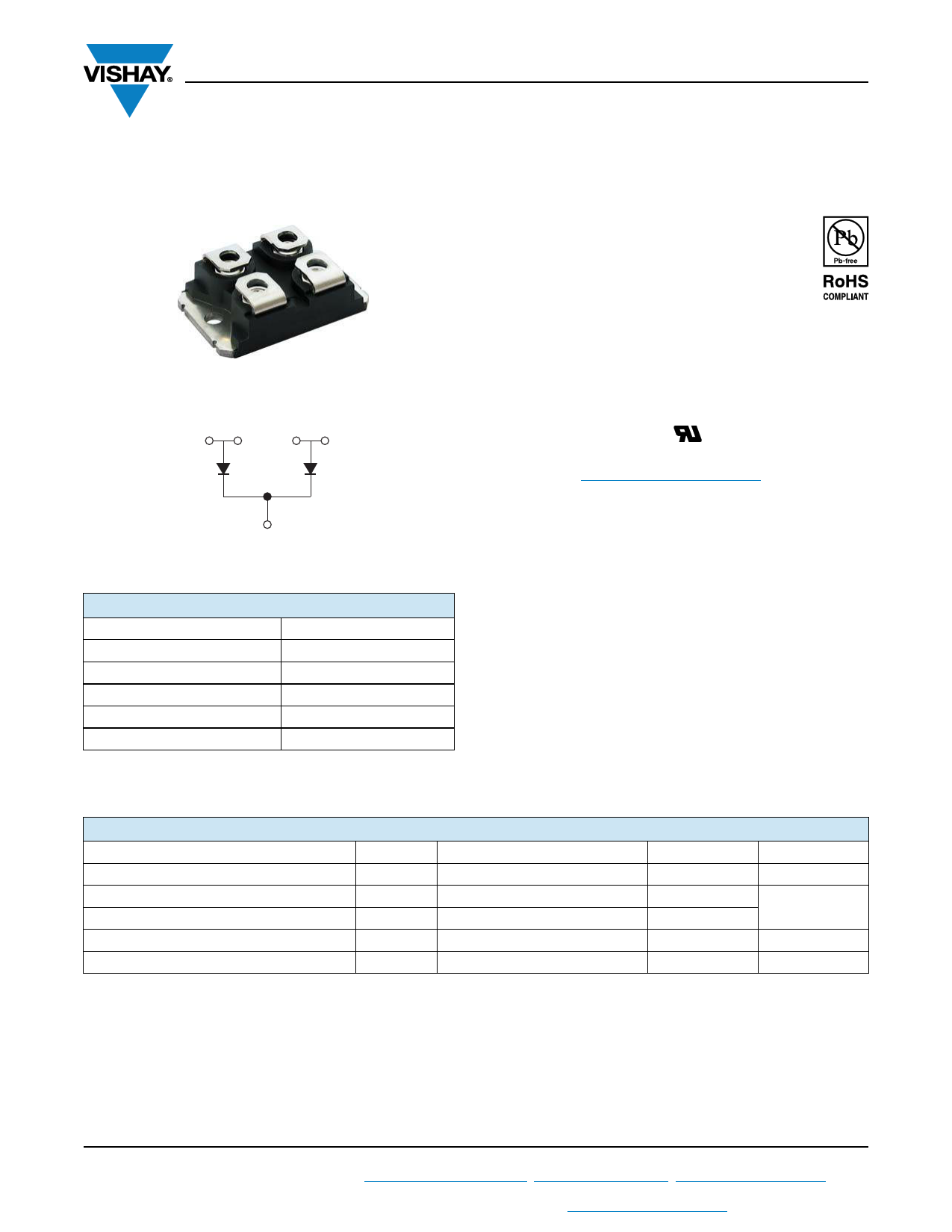
| Descripción | Insulated Ultrafast Rectifier Module | |
| Fabricantes | Vishay | |
| Logotipo | ||
Hay una vista previa y un enlace de descarga de VS-UFB310CB40 (archivo pdf) en la parte inferior de esta página. Total 7 Páginas | ||
|
No Preview Available !
www.vishay.com
VS-UFB310CB40
Vishay Semiconductors
Not Insulated SOT-227 Power Module
Ultrafast Rectifier, 310 A
SOT-227
Anode
12
Anode
34
FEATURES
• Not insulated package
• Ultrafast reverse recovery
• Ultrasoft reverse recovery current shape
• Optimized for power conversion: welding and
industrial SMPS applications
• Plug-in compatible with other SOT-227 packages
• Easy to assemble
• Direct mounting to heatsink
• Designed and qualified for industrial level
• UL approved file E78996
• Material categorization: For definitions of compliance
please see www.vishay.com/doc?99912
Base common cathode
PRODUCT SUMMARY
VR
IF(AV) at TC = 119 °C per module (1)
trr
at TC
Type
400 V
310 A
39 ns
135 °C
Modules - Diode, FRED Pt®
Package
SOT-227
Note
(1) All 4 anode terminals connected
DESCRIPTION
The VS-UFB310CB40 not insulated modules integrate two
state of the art ultrafast recovery rectifiers in the compact,
industry standard SOT-227 package. The planar structure of
the diodes, and the platinum doping life time control,
provide a ultrasoft recovery current shape, together with the
best overall performance, ruggedness and reliability
characteristics.
These devices are thus intended for high frequency
applications in which the switching energy is designed not
to be predominant portion of the total energy, such as in the
output rectification stage of welding machines, SMPS,
DC/DC converters. Their extremely optimized stored charge
and low recovery current reduce both over dissipation in the
switching elements (and snubbers) and EMI/RFI.
ABSOLUTE MAXIMUM RATINGS
PARAMETER
SYMBOL
TEST CONDITIONS
Cathode to anode voltage
Continuous forward current per diode
Single pulse forward current per diode
Maximum power dissipation per module
Operating junction and storage temperatures
VR
IF (1)
IFSM (2)
PD
TJ, TStg
TC = 135 °C
TC = 25 °C
TC = 135 °C
Notes
(1) Both anode terminals connected;
Maximum IRMS current per leg 200 A to do not exceed the maximum temperature of terminals
(2) 10 ms sine or 6 ms rectangular pulse
MAX.
400
155
1300
421
- 55 to 175
UNITS
V
A
W
°C
Revision: 08-Aug-13
1 Document Number: 93608
For technical questions within your region: [email protected], [email protected], [email protected]
THIS DOCUMENT IS SUBJECT TO CHANGE WITHOUT NOTICE. THE PRODUCTS DESCRIBED HEREIN AND THIS DOCUMENT
ARE SUBJECT TO SPECIFIC DISCLAIMERS, SET FORTH AT www.vishay.com/doc?91000
1 page 
www.vishay.com
VS-UFB310CB40
Vishay Semiconductors
VR = 200 V
L = 70 μH
0.01 Ω
D.U.T.
dIF/dt
adjust
G
D
IRFP250
S
Fig. 10 - Reverse Recovery Parameter Test Circuit
IF
0
(3)
trr
ta
tb
(2) IRRM
(4)
Qrr
0.5 IRRM
dI(rec)M/dt (5)
(1) dIF/dt
0.75 IRRM
(1) dIF/dt - rate of change of current
through zero crossing
(2) IRRM - peak reverse recovery current
(3) trr - reverse recovery time measured
from zero crossing point of negative
going IF to point where a line passing
through 0.75 IRRM and 0.50 IRRM
extrapolated to zero current.
(4) Qrr - area under curve defined by trr
and IRRM
Qrr =
trr x IRRM
2
(5) dI(rec)M/dt - peak rate of change of
current during tb portion of trr
Fig. 11 - Reverse Recovery Waveform and Definitions
Revision: 08-Aug-13
5 Document Number: 93608
For technical questions within your region: [email protected], [email protected], [email protected]
THIS DOCUMENT IS SUBJECT TO CHANGE WITHOUT NOTICE. THE PRODUCTS DESCRIBED HEREIN AND THIS DOCUMENT
ARE SUBJECT TO SPECIFIC DISCLAIMERS, SET FORTH AT www.vishay.com/doc?91000
5 Page | ||
| Páginas | Total 7 Páginas | |
| PDF Descargar | [ Datasheet VS-UFB310CB40.PDF ] | |
Hoja de datos destacado
| Número de pieza | Descripción | Fabricantes |
| VS-UFB310CB40 | Insulated Ultrafast Rectifier Module | Vishay |
| Número de pieza | Descripción | Fabricantes |
| SLA6805M | High Voltage 3 phase Motor Driver IC. |
Sanken |
| SDC1742 | 12- and 14-Bit Hybrid Synchro / Resolver-to-Digital Converters. |
Analog Devices |
|
DataSheet.es es una pagina web que funciona como un repositorio de manuales o hoja de datos de muchos de los productos más populares, |
| DataSheet.es | 2020 | Privacy Policy | Contacto | Buscar |