|
|
|
PDF IR2177S Data sheet ( Hoja de datos )
| Número de pieza | IR2177S | |
| Descripción | Phase Current Sensor IC | |
| Fabricantes | International Rectifier | |
| Logotipo | ||
Hay una vista previa y un enlace de descarga de IR2177S (archivo pdf) en la parte inferior de esta página. Total 20 Páginas | ||
|
No Preview Available !
Data Sheet No. PD60233 revB
IR2277S/IR2177S(PbF)
Phase Current Sensor IC for AC motor control
Features
• Floating channel up to 600 V for IR2177 & 1200 V for
IR2277
• Synchronous sampling measurement system
• High PWM noise (ripple) rejection capability
• Digital PWM output
• Fast Over Current detection
• Suitable for bootstrap power supplies
• Low sensing latency (<7.5 µsec @20kHz)
• Ratiometric analog output suitable for DSP A/D interface
Product Summary
VOFFSET (max) IR2277
1200 V
IR2177 600 V
Vin range
±250mV
Bootstrap supply range
8-20 V
Floating channel quiescent
current (max)
Sensing latency (max)
Throughput
Over Current threshold
(max)
2.2 mA
7.5 µsec
(@20kHz)
40ksample/sec
(@20kHz)
±470 mV
Description
IR2177/IR2277 is a high voltage, high speed, single phase current
sensor interface for AC motor drive applications. The current is
sensed by an external shunt resistor. The IC converts the analog
voltage into a time interval through a precise circuit that also
performs a very good ripple rejection showing small group delay.
The time interval is level shifted and given to the output both as a
PWM signal (PO) and analog voltage (OUT). The analog voltage is
proportional to the measured current and is ratio metric with respect
to an externally provided voltage reference. The max throughput is
40 ksample/sec suitable for up to 20 kHz asymmetrical PWM
modulation and max delay is <7.5 µsec (@20kHz). Also a fast over
current signal is provided for IGBT protection.
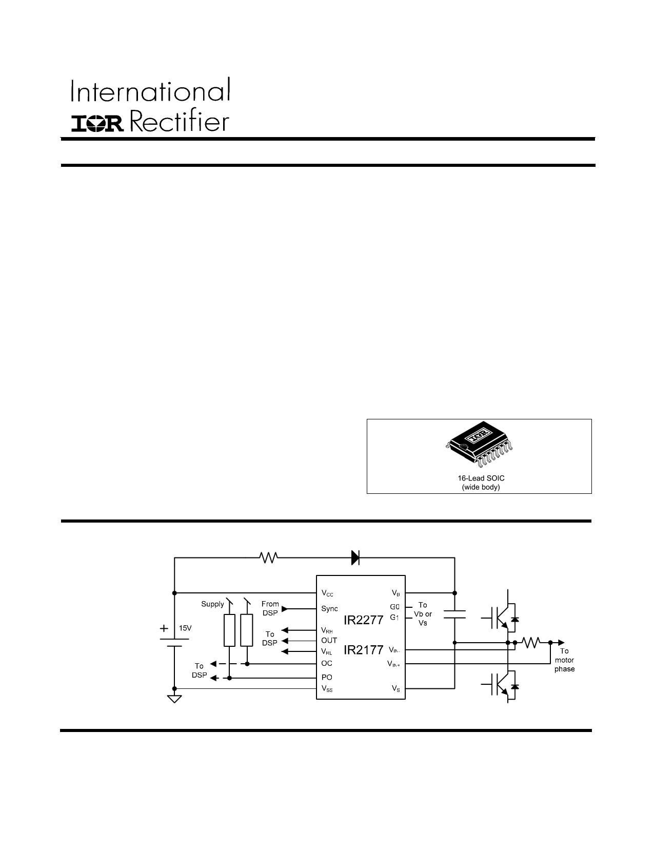
Typical Connection
Package
(Please refer to
Lead Assignments
for correct pin
configuration. This
diagram shows
electrical
connections only)
1
www.irf.com
1 page 
IR2277S/IR2177S(PbF)
Pin: OUT, VRH, VRL
Symbol
Definition
RREF
Vaos
∆ Vaos /
∆Tj
∆Vaos
VRH to VRL input resistance
Input offset voltage measured by
analog output
Input offset voltage temperature drift
∆offset between samples on channel1
and channel2 measured at OUT
(Note1)
Ga Analog Output Gain
∆Ga / ∆Tj Analog Output Gain Temperature Drift
CMRR
OUT
Analog Output common mode (VS
offset) rejection
VOUTlin
Out Linearity
∆ Vlin /
∆Tj
PSRR
OUT
Out Linearity Temperature Drift
PSRR for Analog Output
VOUTl
Vout Low Saturation
VOUTh
Vout High Saturation
Note1: Refer to PO output description for channels definition
Min.
36
-100
-20%
30
0
VRH+0.2
Typ.
TBD
2VR
TBD
100
0.3
TBD
Max.
84
50
Units
kΩ
mV
µV / ºC
+20%
V/V
ºC-1
dB
0.7
100
50
VRH+0.7
%
%/ºC
dB
mV
V
Test
Conditions
fsync = 8kHz, 20
kHz
Measured by
analog output
fsync = 8kHz, 20
kHz
VR=VRH-VRL=3V
Vs-Vss=0V,
600V
fsync = 10kHz
fsync = 8kHz,
20kHz
fsync = 8kHz,
20kHz
VCC= VBS =8V,
20V
Vin= -500mV
Vin = +500mV
5 www.irf.com
5 Page 
1 Device Description
1.1 SYNC input
Sync input clocks the whole device. In order to
make the device work properly it must be
synchronous with the triangular PWM carrier as
shown in Figure 8.
SYNC pin is internally pulled-down (10 kΩ) to VSS.
1.2 PWM Output (PO)
PWM output is an open collector output (active low).
It must be pulled-up to proper supply with an
external resistor (suggested value between 500Ω
and 10kΩ).
Supply
τ
Vlow
Figure 7: PO rising and falling slopes
PO pull-up resistor determines the rising slope of
the PO output and the lower value of PO as shown
in Figure 7, where τ = RC , C is the total PO pin
capacitance and R is the pull-up resistance.
Vlow
=
Supply ⋅
Ron
R on + R pull−up
where Ron is the internal open collector resistance
and Rpull-up is the external pull-up resistance.
PO duty cycle is defined for active low logic by the
following formula:
Eq. 1
Toff _ cycle _ n+1
D =n
Tcycle _ n
PO duty cycle (Dn) swings between 10% and 30%.
Zero input voltage corresponds to 20% duty cycle.
IR2277S/IR2177S(PbF)
A residual offset can be read in PO duty cycle
according to VPOs (see Static electrical
characteristics).
According to
Figure 8, it can be assumed that odd cycles are
represented by SYNC at high level (let’s name
channel 1 the output related to this state of SYNC)
and even cycles represented by SYNC at low level
(channel 2).
The two channels are independent in order to
provide the correct duty cycle value of PO even for
non-50% duty cycle of SYNC signal. Small variation
of SYNC duty cycle are then allowed and
automatically corrected when calculating the duty
cycle using Eq. 1.
However, channel 1 and channel 2 can have a
difference in offset value which is specified in
∆VPOS (see Static electrical characteristics).
To implement a correct offset compensation of PO
duty cycle and analog OUT, each channel must be
compensated separately.
1.3 Over Current output (OC)
OC output is an open drain pin (active low).
A simplified block diagram of the over current circuit
is shown in the
Figure 9.
Over current is detected when |Vin|=|Vinp-Vinm|>VOCth.
If an event of over current lasts longer than tdOCon,
OC pin is forced to VSS and remains latched until
PO is externally forced low for at least tOCoff (see
timing on Figure 4). During an over current event
(OC is low), PO is off (pulled-up by external
resistor).
If OC is reset by PO and over current is still active,
OC pin will be forced low again by the next edge of
SYNC signal.
To reset OC state PO must be forced to VSS for at
least TOCoff.
• Autoreset function
The autoreset function consists in clearing
automatically the OC fault.
To enable the autoreset function, simply short
circuit the OC pin with the PO pin.
11 www.irf.com
11 Page | ||
| Páginas | Total 20 Páginas | |
| PDF Descargar | [ Datasheet IR2177S.PDF ] | |
Hoja de datos destacado
| Número de pieza | Descripción | Fabricantes |
| IR21771S | Phase Current Sensor IC | International Rectifier |
| IR2177S | Phase Current Sensor IC | International Rectifier |
| IR2177SPBF | Phase Current Sensor IC | International Rectifier |
| Número de pieza | Descripción | Fabricantes |
| SLA6805M | High Voltage 3 phase Motor Driver IC. |
Sanken |
| SDC1742 | 12- and 14-Bit Hybrid Synchro / Resolver-to-Digital Converters. |
Analog Devices |
|
DataSheet.es es una pagina web que funciona como un repositorio de manuales o hoja de datos de muchos de los productos más populares, |
| DataSheet.es | 2020 | Privacy Policy | Contacto | Buscar |