|
|
|
PDF GW40NC60KD Data sheet ( Hoja de datos )
| Número de pieza | GW40NC60KD | |
| Descripción | 40A - 600V - short circuit rugged IGBT | |
| Fabricantes | STMicroelectronics | |
| Logotipo | ||
Hay una vista previa y un enlace de descarga de GW40NC60KD (archivo pdf) en la parte inferior de esta página. Total 13 Páginas | ||
|
No Preview Available !
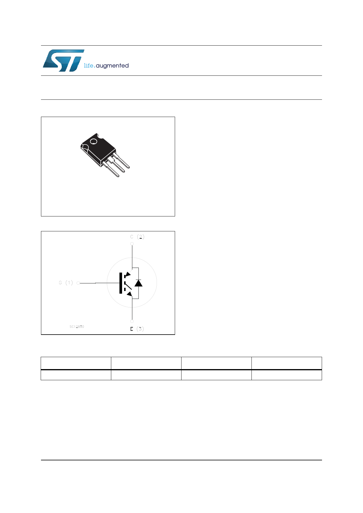
STGW40NC60KD
600 V, 40 A short-circuit rugged IGBT
3
2
1
TO-247
Figure 1. Internal schematic diagram
Datasheet - production data
Features
• Low on-voltage drop (VCE(sat))
• Low Cres / Cies ratio (no cross conduction
susceptibility)
• Short-circuit withstand time 10 µs
• IGBT co-packaged with ultra fast free-wheeling
diode
Applications
• High frequency inverters
• Motor drivers
Description
This IGBT utilizes the advanced PowerMESH™
process resulting in an excellent trade-off
between switching performance and low on-state
behavior.
Order code
STGW40NC60KD
Table 1. Device summary
Marking
Package
GW40NC60KD
TO-247
Packaging
Tube
March 2014
This is information on a product in full production.
DocID14807 Rev 2
1/13
www.st.com
13
1 page 
STGW40NC60KD
Electrical characteristics
Table 6. Switching on/off (inductive load)
Symbol
Parameter
Test conditions
Min. Typ. Max. Unit
td(on)
tr
(di/dt)on
td(on)
tr
(di/dt)on
tr(Voff)
td(off)
tf
Turn-on delay time
Current rise time
Turn-on current slope
Turn-on delay time
Current rise time
Turn-on current slope
Off voltage rise time
Turn-off delay time
Current fall time
tr(Voff)
td(off)
tf
Off voltage rise time
Turn-off delay time
Current fall time
VCC = 480 V, IC = 30 A
RG=10 Ω, VGE= 15 V,
(see Figure 17)
46 ns
- 18.5 - ns
1530
A/µs
VCC = 480 V, IC = 30 A
45 ns
RG=10 Ω, VGE= 15 V,
- 19
- ns
TC= 125 °C (see Figure 17)
1400
A/µs
VCC = 480 V, IC = 30 A
RG=10 Ω, VGE= 15 V,
(see Figure 17)
38 ns
- 164 - ns
87 ns
Vcc = 480 V, IC = 30 A,
RG = 10 Ω, VGE = 15 V
TC= 125 °C
(see Figure 17)
70 ns
- 208 - ns
130 ns
Table 7. Switching energy (inductive load)
Symbol
Parameter
Test conditions
Min. Typ. Max. Unit
Eon
Eoff (1)
Ets
Turn-on switching losses
Turn-off switching losses
Total switching losses
Eon
Eoff (1)
Ets
Turn-on switching losses
Turn-off switching losses
Total switching losses
VCC = 480 V, IC = 30 A
RG= 10 Ω, VGE= 15 V,
(see Figure 17)
VCC = 480 V, IC = 30 A
RG= 10 Ω, VGE= 15 V,
TC= 125 °C
(see Figure 17)
595
- 716 -
1311
808
- 1200 -
2008
µJ
µJ
µJ
µJ
µJ
µJ
1. Turn-off losses include also the tail of the collector current.
Symbol
Table 8. Collector-emitter diode
Parameter
Test conditions
VF Forward on-voltage
IF = 30 A
IF = 30 A, TC = 125 °C
trr Reverse recovery time
IF = 30 A,VR = 50 V,
Qrr Reverse recovery charge di/dt = 100 A/μs
Irrm Reverse recovery current (see Figure 20)
trr
Qrr
Reverse recovery time
Reverse recovery charge
IF = 30 A,VR = 50 V,
TC =125 °C, di/dt = 100
A/μs
Irrm Reverse recovery current (see Figure 20)
Min. Typ. Max. Unit
2.4
--
1.8
45
- 56 -
2.55
V
V
ns
nC
A
100 ns
- 290 - nC
5.8 A
DocID14807 Rev 2
5/13
5 Page 
STGW40NC60KD
Dim.
A
A1
b
b1
b2
c
D
E
e
L
L1
L2
∅P
∅R
S
Package mechanical data
Table 9. TO-247 mechanical data
mm.
Min.
4.85
2.20
1.0
2.0
3.0
0.40
19.85
15.45
5.30
14.20
3.70
3.55
4.50
5.30
Typ.
5.45
18.50
5.50
Max.
5.15
2.60
1.40
2.40
3.40
0.80
20.15
15.75
5.60
14.80
4.30
3.65
5.50
5.70
DocID14807 Rev 2
11/13
11 Page | ||
| Páginas | Total 13 Páginas | |
| PDF Descargar | [ Datasheet GW40NC60KD.PDF ] | |
Hoja de datos destacado
| Número de pieza | Descripción | Fabricantes |
| GW40NC60KD | 40A - 600V - short circuit rugged IGBT | STMicroelectronics |
| Número de pieza | Descripción | Fabricantes |
| SLA6805M | High Voltage 3 phase Motor Driver IC. |
Sanken |
| SDC1742 | 12- and 14-Bit Hybrid Synchro / Resolver-to-Digital Converters. |
Analog Devices |
|
DataSheet.es es una pagina web que funciona como un repositorio de manuales o hoja de datos de muchos de los productos más populares, |
| DataSheet.es | 2020 | Privacy Policy | Contacto | Buscar |