|
|
|
PDF 20MU11 Data sheet ( Hoja de datos )
| Número de pieza | 20MU11 | |
| Descripción | COLOR TELEVISION SERVICE MANUAL | |
| Fabricantes | Sharp | |
| Logotipo | ||
Hay una vista previa y un enlace de descarga de 20MU11 (archivo pdf) en la parte inferior de esta página. Total 30 Páginas | ||
|
No Preview Available !
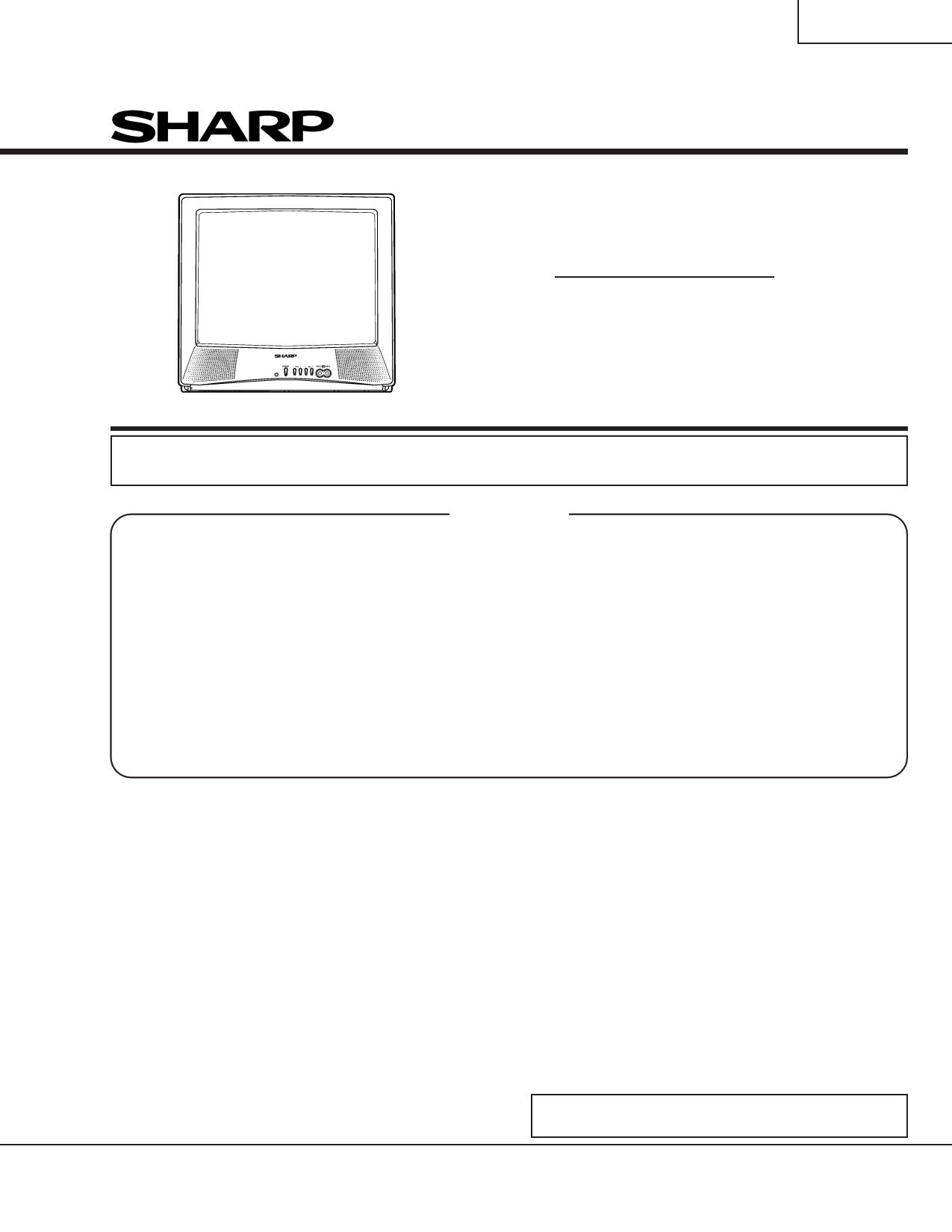
20MU11
SERVICE MANUAL
COLOR TELEVISION
Chassis No. SN-80
MODELS 20MU11
In the interests of user-safety (Required by safety regulations in some countries) the set should be restored to its
original condition and only parts identical to those specified should be used.
CONTENTS
Page
» ELECTRICAL SPECIFICATIONS ......................................................................................................... 1
» IMPORTANT SERVICE SAFETY PRECAUTION ................................................................................. 2
» LOCATION OF USER'S CONTROL ..................................................................................................... 6
» INSTALLATION AND SERVICE INSTRUCTIONS ................................................................................ 7
» CHASSIS LAYOUT ............................................................................................................................ 12
» BLOCK DIAGRAM ............................................................................................................................. 13
» SCHEMATIC DIAGRAMS .................................................................................................................. 14
» PRINTED WIRING BOARD ASSEMBLIES ........................................................................................ 18
» REPLACEMENT PARTS LIST ........................................................................................................... 23
» PACKING OF THE SET ..................................................................................................................... 35
ELECTRICAL SPECIFICATIONS
POWER INPUT ................................ 120 V AC 60 Hz
POWER RATING ............................................. 82 W
PICTURE SIZE ....................... 1,194cm2 (185sq inch)
CONVERGENCE ........................................ Magnetic
SWEEP DEFLECTION ................................ Magnetic
FOCUS ........................... Hi-Bi-Potential Electrostatic
INTERMEDIATE FREQUENCIES
Picture IF Carrier Frequency ................. 45.75 MHz
Sound IF Carrier Frequency .................. 41.25 MHz
Color Sub-Carrier Frequency ................ 42.17 MHz
(Nominal)
AUDIO POWER
OUTPUT RATING ........... 0.9 W (at 10% distortion)
SPEAKER
SIZE .................................................. 8 cm (Round)
VOICE COIL IMPEDANCE ........... 8 ohm at 400 Hz
ANTENNA INPUT IMPEDANCE
VHF/UHF ................................ 75 ohm Unbalanced
TUNING RANGES
VHF-Channels .......................................... 2 thru 13
UHF-Channels........................................ 14 thru 69
CATV Channels ...................................... 1 thru 125
(EIA, Channel Plan U.S.A.)
Specifications are subject to change without
prior notice.
SHARP CORPORATION
This document has been published to be used for after
sales service only.
1 The contents are subject to change without notice.
1 page 
20MU11
INSTALLATION AND SERVICE INSTRUCTIONS
Note: (1) When performing any adjustments to resistor controls and transformers use non-metallic
screwdrivers or TV alignment tools.
(2) Before performing adjustments, the TV set must be on at least 15 minutes.
CIRCUIT PROTECTION
HIGH VOLTAGE CHECK
The receiver is protected by a 4.0A fuse (F701),
mounted on PWB-A, wired into one side of the AC
line input.
X-RADIATION PROTECTOR CIRCUIT TEST
After service has been performed on the horizontal
deflection system, high voltage system, +B system,
test the X-Radiation protection circuit to ascertain
proper operation as follows:
1) Apply 120V AC using a variac transformer for
accurate input voltage.
2) Allow for warm up and adjust all customer controls
for normal picture and sound.
3) Receive a good local channel.
4) Connect a digital voltmeter to TP653 and make sure
that the voltmeter reads 21.3 ±1.5 V.
5) Apply external 28.9V DC at TP653 by using an
external DC supply, TV must be shut off.
6) To reset the protector, unplug the AC cord and make
a short circuit between TP651 and TP652. Now make
sure that normal picture appears on the screen.
7) If the operation of the horizontal oscillator does not
stop in step 5, the circuit must be repaired before
the set is returned to the customer.
High voltage is not adjustable but must be checked
to verify that the receiver is operating within safe
and efficient design limitations as specified checks
should be as follows:
1. Connect an accurate high voltage meter between
ground and anode of picture tube.
2. Operate receiver for at least 15 minutes at 120V AC
line voltage, with a strong air signal or a properly
tuned in test signal.
3. Enter the service mode and select the service
adjustment "S19" and Bus data "01" (Y-mute on).
4. The voltage should be approximately, 26.0kV (at zero
beam).
If a correct reading cannot be obtained, check
circuitry for malfunctioning components. After the
voltage test, make Y-mute off to the normal mode.
5
5 Page 
BLOCK DIAGRAM
H
20MU11
G
F
E
D
C
B
A
12345 6
11
11 Page | ||
| Páginas | Total 30 Páginas | |
| PDF Descargar | [ Datasheet 20MU11.PDF ] | |
Hoja de datos destacado
| Número de pieza | Descripción | Fabricantes |
| 20MU11 | COLOR TELEVISION SERVICE MANUAL | Sharp |
| Número de pieza | Descripción | Fabricantes |
| SLA6805M | High Voltage 3 phase Motor Driver IC. |
Sanken |
| SDC1742 | 12- and 14-Bit Hybrid Synchro / Resolver-to-Digital Converters. |
Analog Devices |
|
DataSheet.es es una pagina web que funciona como un repositorio de manuales o hoja de datos de muchos de los productos más populares, |
| DataSheet.es | 2020 | Privacy Policy | Contacto | Buscar |