|
|
|
PDF XC9128 Data sheet ( Hoja de datos )
| Número de pieza | XC9128 | |
| Descripción | Step-Up DC/DC Converters | |
| Fabricantes | Torex Semiconductor | |
| Logotipo | ||
Hay una vista previa y un enlace de descarga de XC9128 (archivo pdf) en la parte inferior de esta página. Total 26 Páginas | ||
|
No Preview Available !
XC9128/XC9129 Series
1A Driver Transistor Built-In, Step-Up DC/DC Converters
ETR0411-011
GreenOperation Compatible
GENERAL DESCRIPTION
The XC9128/XC9129 series are synchronous step-up DC/DC converters with a 0.2Ω (TYP.) N-channel driver transistor and a
synchronous 0.2Ω (TYP.) P-channel switching transistor built-in. A highly efficient and stable current can be supplied up to
1.0A by reducing ON resistance of the built-in transistors. With a high switching frequency of 1.2MHz, a small inductor is
selectable making the series ideally suited for applications requiring low profile or space saving solutions. With the MODE
pin, the series provides mode selection of PWM control or PFM/PWM automatic switching control. In the PWM/PFM
automatic switching mode, the series switches from PWM to PFM to reduce switching loss when load current is small.
When load current is large, the series switches automatically to the PWM mode so that high efficiency is achievable over a
wide range of load conditions. The series also provides small output ripple from light to large loads by using the built-in
circuit which enables the smooth transition between PWM and PFM. With a adaptor enable function of the XC9128 series,
when a voltage higher than the input voltage is applied to the output, the input and the output become isolated making it
possible for the IC to work in parallel with the likes of an AC adaptor.
APPLICATIONS
Digital audio equipment
Digital still cameras / Camcorders
Computer Mouses
Multi-function power supplies
FEATURES
High Efficiency, Large Current Step-Up Converter
Output Current
Input Voltage Range
: 150mA VOUT=3.3V, VIN=0.9V
500mA VOUT=3.3V, VIN=1.8V
: 0.8V~6.0V
Output Voltage Setting
: 1.8V~5.3V (Externally set)
Range
Set up freely with a reference voltage
supply of 0.45V ( 0.010V) & external
components
Oscillation Frequency
: 1.2MHz (Fixed oscillation frequency
accuracy ±15%)
Input Current
: 1.0A
Maximum Current Limit
: 1.2A (MIN.), 2.0A (MAX.)
Control
: PWM, PWM/PFM control
externally selectable
High Speed
Transient Response
Protection Circuits
:100mV @ VOUT=3.3V,
VIN=1.8V, IOUT=10mA→100mA
: Thermal shutdown
Integral latch method (Over current
limit)
Soft-Start Time
: 5ms (TYP.) internally set
Ceramic Capacitor Compatible
Adaptor Enable Function (XC9128 series)
Flag Output (XC9128 series) : Open-drain output
Operating Ambient Temperature : - 40 +85
Packages
: MSOP-10, USP-10B
Environmentally Friendly : EU RoHS Compliant, Pb Free
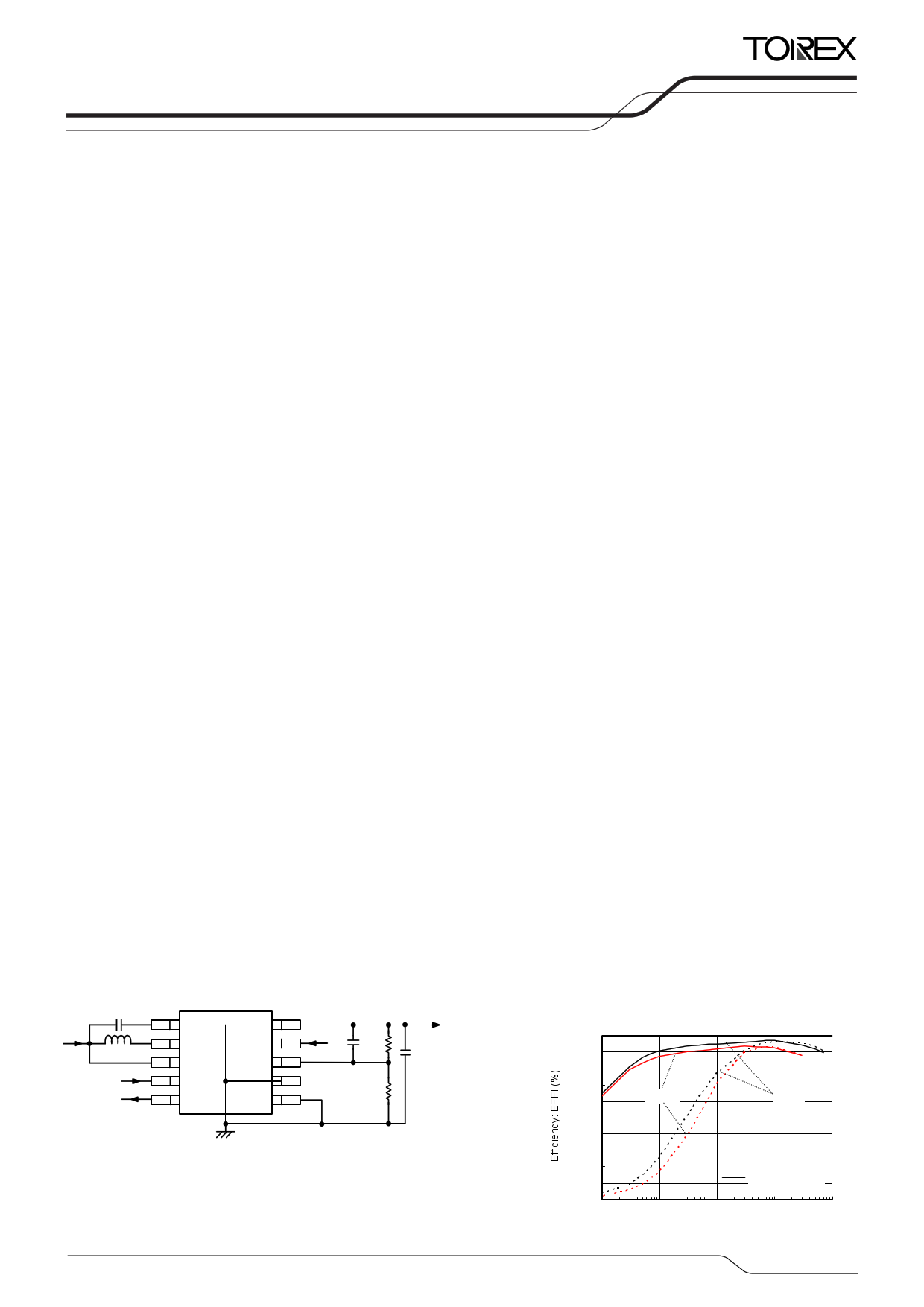
TYPICAL APPLICATION CIRCUIT
TYPICAL PERFORMANCE
CHARACTERISTICS
Efficiency vs. Output Current
XC9128B45CD
100
90
80
70
60
50
40
30
20
10
0
0.1
1.8V
3.0V
1 10 100
Output Current: I OUT (mA)
1000
1/26
1 page 
BLOCK DIAGRAM
XC9128 Series
XC9128/XC9129
Series
* XC9129 Series
The XC9129 series does not have AEN/ pin and FO pin.
ABSOLUTE MAXIMUM RATINGS
PARAMETER
SYMBOL
RATINGS
VOUT Pin Voltage
VOUT
- 0.3 6.5
AEN/ Pin Voltage (*2)
FO Pin Voltage (*2)
FO Pin Current (*2)
VAEN/
VFO
IFO
- 0.3 6.5
- 0.3 6.5
10
FB Pin Voltage
VFB
- 0.3 6.5
BAT Pin Voltage
VBAT
- 0.3 6.5
MODE Pin Voltage
VMODE
- 0.3 6.5
EN Pin Voltage
VEN
- 0.3 6.5
LX Pin Voltage
LX Pin Current
Power Dissipation
MSOP-10
USP-10B
VLx
ILx
Pd
- 0.3 VOUT+0.3
2000
350 (*1)
150
Operating Ambient Temperature
Topr
- 40 +85
Storage Temperature
Tstg
- 55 +125
AGND, PGND is the standard voltage for all of voltages.
*1: When implemented on a PCB.
*2: The XC9129 series does not have AEN/ pin and FO pin. These pins are available only in the XC9128 series.
Ta=25
UNITS
V
V
V
mA
V
V
V
V
V
mA
mW
oC
oC
5/26
5 Page 
XC9128/XC9129
Series
NOTE ON USE (Continued)
7. P-ch synchronous switching transistor operation
The parasitic diode of the P-ch synchronous transistor is placed between Lx (anode) and VOUT (cathode), so that the
power line can not be turned off from Lx to VOUT. On the other hand, the power line switch from VOUT to Lx is shown in the
table below.
XC9128 Series
EN Pin
H
H
L
L
AEN/Pin
H
L
H
L
P-channel Synchronous Switch Transistor Operation
OFF
Switching
OFF
Undefined
XC9129 Series
EN Pin
H
L
P-channel Synchronous Switch Transistor Operation
Switching
Undefined
With the XC9128B/XC9129B series, when step-up operation stops as a result of the latch condition working when the
maximum current limit level is reached, the synchronous P-channel transistor will remain ON.
8. The maximum current limiter controls the limit of the N-channel driver transistor by monitoring current flow. This function
does not limit the current flow of the P-channel synchronous transistor.
9. The integral latch time of the XC9128B/XC9129B series could be released from the maximum current detection state as a
result of board mounting conditions. This may extend integral latch time or the level required for latch operation to
function may not be reached. Please connect the output capacitor as close to the IC as possible.
10. With the XC9128B/XC9129B series, when the EN pin is left open or applied in the range of 0.2V 0.65V, the integral
latch or the VLVP may not be able to release. Please make sure that the EN pin voltage is less than 0.2V or more than
0.65V, or use the XC9128D/XC9129D series which does not have the integral latch and the LVP functions.
11. With the XC9128B/XC9129B series, please make the VOUT pin voltage become more than 1.5V within the soft-start time,
otherwise the VLVP is detected. Also, the operation may become unstable, please test and verify the operation in the
actual circuits thoroughly before use.
12. When used in small step-up ratios, the device may skip pulses during PWM control mode.
11/26
11 Page | ||
| Páginas | Total 26 Páginas | |
| PDF Descargar | [ Datasheet XC9128.PDF ] | |
Hoja de datos destacado
| Número de pieza | Descripción | Fabricantes |
| XC9128 | Step-Up DC/DC Converters | Torex Semiconductor |
| XC9129 | Step-Up DC/DC Converters | Torex Semiconductor |
| Número de pieza | Descripción | Fabricantes |
| SLA6805M | High Voltage 3 phase Motor Driver IC. |
Sanken |
| SDC1742 | 12- and 14-Bit Hybrid Synchro / Resolver-to-Digital Converters. |
Analog Devices |
|
DataSheet.es es una pagina web que funciona como un repositorio de manuales o hoja de datos de muchos de los productos más populares, |
| DataSheet.es | 2020 | Privacy Policy | Contacto | Buscar |