|
|
|
PDF ACPL-M46T Data sheet ( Hoja de datos )
| Número de pieza | ACPL-M46T | |
| Descripción | Automotive Intelligent Power Module | |
| Fabricantes | AVAGO | |
| Logotipo | ||
Hay una vista previa y un enlace de descarga de ACPL-M46T (archivo pdf) en la parte inferior de esta página. Total 13 Páginas | ||
|
No Preview Available !
ACPL-M46T
Automotive Intelligent Power Module
with R2Coupler™ Isolation and Small Outline, 5 Lead Package
Data Sheet
Lead (Pb) Free
RoHS 6 fully
compliant
RoHS 6 fully compliant options available;
-xxxE denotes a lead-free product
Description
The A CPL-M46T c onsists of a AlG aAs optically c oupled
to an int egrated high gain phot o det ector. M inimized
propagation dela y diff erence bet ween devic es make
these optocouplers excellent solutions for improving au-
tomotive inverter efficiency through reduced switching
dead time.
Specification and performance plots are given for typical
IPM applications.
Avago R 2Coupler isolation pr oducts pr ovide the r ein-
forced insulation and reliability needed for critical in au-
tomotive and high temperature industrial applications.
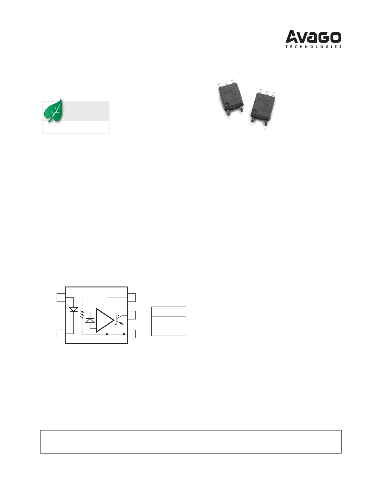
Schematic Diagram
ANODE 1
CATHODE 3
SHIELD
6 VCC Truth Table
5 VOUT LED VO
ON L
4 GND OFF H
The connection of a 0.1 μF b ypass capacitor between pins 4 and 6 is
recommended.
Features
Performance specified for common IPM applications
over automotive temperature range: -40°C to 125°C
Fast maximum propagation delays
- t PHL & tPLH = 550 ns
Minimized Pulse Width Distortion (PWD = 370 ns)
Very high Common Mode Rejection (CMR):
15 kV/μs at VCM = 1500V
CTR > 44% at IF = 10 mA
Qualifi ed to AEC-Q100 Test Guidelines
Saf ety approval
- UL recognized per UL1577 (file no. E55361)
4000 Vrms for 1 minute
- IEC/EN/DIN EN 60747-5-2 Approved
- CSA Approved
Applic ations
Automotive IP M isolation f or batt ery management
system and motor control
Isolated IGBT/MOSFET gate drive
AC and brushless dc motor drives
Industrial in verters f or po wer supplies and mot or
controls
CAUTION: It is advised that normal static precautions be taken in handling and assembly
of this component to prevent damage and/or degradation which may be induced by ESD.
http://www.Datasheet4U.com
1 page 
Electrical Specifications
Over recommended operating conditions unless otherwise specified:
TA = -40°C to +125°C, VCC = +4.5 V to 30 V, IF(on) = 10 mA to 20 mA, VF(off) = -5 V to 0.8 V
Parameter
Symbol Min. Typ.* Max. Units Test Conditions
C urrent Transfer Ratio
Low Level Output
C urrent
CTR
IOL 4.4
44
90
9.0
% IF = 10 mA, VO = 0.6 V
mA IF = 10 mA, VO = 0.6 V
Low Level Output Voltage
I nput Threshold Current
High Level Output
C urrent
VOL
ITH
IOH
0.3 0.6 V IO = 2.4 mA
1.5 5.0 mA VO = 0.8 V, IO = 0.75 mA
5 50 μA VF = 0.8 V
High Level Supply Current
Low Level Supply Current
I nput Forward Voltage
T emperature Coefficient
of Forward Voltage
ICCH
ICCL
VF 1.45
1.25
ΔVF/ΔTA
0.6
0.6
1.5
1.5
-1.5
1.3 mA VF = 0.8 V, VO = Open
1.3 mA IF = 10 mA, VO = Open
1.75 V TA = 25°C , IF = 10 mA
1.85 V IF = 10 mA
mV/°C IF = 10 mA
Input Reverse Breakdown
V oltage
BVR 5
V IR = 10 μA
I nput Capacitance
I nput-Output
I nsulation Voltage
Resistance (Input - Output)
C apacitance
(Input - Output)
CIN
VISO 4000
RI-O
CI-O
90
1014
0.6
pF f = 1 MHz, VF = 0 V
VRMS RH < 50%, t = 1 min,
TA = 25°C
Ω VI-O = 500 Vdc
pF f = 1 MHz
*All typical values at 25°C, VCC = 15 V.
Fig. Note
1
2,3
24
4
4
4
5
2, 3
6
6
5
5 Page 
+5 V 1
310 W
3
CMOS
SHIELD
6
0.1 μF
5
4
20 kΩ
VOUT
100 pF
V=1C5CV
+–
*100 pF TOTAL
CAPACITANCE
1
3
CLEDP
CLEDN
6
5
4
Figure 13. Recommended LED Drive Circuit.
Figure 14. Optocoupler Input ot Output Capacitance Model for Unshielded
Optocouplers.
1 CLEDP
CLED01
6
5
3 CLEDN SHIELD
4
Figure 15. Optocoupler Input to Output Capacitance Model for Shielded
Optocouplers.
+5 V
1
310 Ω
CMOS
3
SHIELD
6
0.1 μF
5
4
20 kΩ
VOUT
100 pF
V=1C5CV
+–
*100 pF TOTAL
CAPACITANCE
Figure 16. LED Drive Circuit with Resistor Connected to LED Anode (Not
Recommended).
ITOTAL*
ICLEDP
1
300 Ω
IF
ICLED01
CLED01
6
5 VOUT
3 CLEDN SHIELD
4
* THE ARROWS INDICATE THE DIRECTION OF CURRENT
FLOW FOR +dVCM/dt TRANSIENTS.
+
VCM
20 kΩ
100 pF
Figure 17. AC Equivalent Circuit for Figure 16 during Common Mode
Transients.
1
+ VR** –
CLEDP
CLED01
6
5 VOUT
300 Ω
CLEDN
3
ICLEDN* SHIELD
4
* THE ARROWS INDICATE THE DIRECTION OF CURRENT
** OFLPOTWIONFOALRC+LdAVMCMPI/NdtGTRDAIONDSEIEFNOTRS.IMPROVED CMH
PERFORMANCE. VR < VF (OFF) DURING +dVCM/dt.
+
VCM
20 kΩ
100 pF
Figure 18. AC Equivalent Circuit for Figure 13 during Common Mode
Transients.
11
11 Page | ||
| Páginas | Total 13 Páginas | |
| PDF Descargar | [ Datasheet ACPL-M46T.PDF ] | |
Hoja de datos destacado
| Número de pieza | Descripción | Fabricantes |
| ACPL-M46T | Automotive Intelligent Power Module | AVAGO |
| Número de pieza | Descripción | Fabricantes |
| SLA6805M | High Voltage 3 phase Motor Driver IC. |
Sanken |
| SDC1742 | 12- and 14-Bit Hybrid Synchro / Resolver-to-Digital Converters. |
Analog Devices |
|
DataSheet.es es una pagina web que funciona como un repositorio de manuales o hoja de datos de muchos de los productos más populares, |
| DataSheet.es | 2020 | Privacy Policy | Contacto | Buscar |