|
|
|
PDF CAT7580 Data sheet ( Hoja de datos )
| Número de pieza | CAT7580 | |
| Descripción | Synchronous and Rectified Buck PWM Controller | |
| Fabricantes | Chip Advanced Tech | |
| Logotipo | ||
Hay una vista previa y un enlace de descarga de CAT7580 (archivo pdf) en la parte inferior de esta página. Total 11 Páginas | ||
|
No Preview Available !
CAT7580
Synchronous and Rectified Buck PWM Controller
FEATURES:
Input Voltage Range from 4.5 V to 13.2 V
320 kHz Internal Oscillator
Boost Pin Operates to 26.5 V
Voltage Mode PWM Control
0.8 V ~1.5% Internal Reference Voltage
Adjustable Output Voltage
Internal Soft-Start
Internal 1.5 A Gate Drivers
Adaptive Non-Overlap Circuit
90% Max Duty Cycle
Input UVLO
Over-Temperature Protection
Fully Specified over -40C to 85C
SOP8 Package
RoHS Compliant (100% Pb-free available)
GENERAL DESCRIPTION:
The CAT7580 is a voltage mode PWM
controller designed to operate from a 5.0 V to
12.0 V supply and produce an output voltage as
low as 0.8 V. This 8-pin device provides an
optimal level of integration to reduce size and
cost of the power supply. The CAT7580 has a
fixed 320 kHz oscillator and soft-start function.
The CAT7580 provides a 1.5 A floating gate
driver design to drive N-Channel MOSFETs in a
synchronous
configuration.
Adaptive
non-overlap circuitry reduces switching losses
by preventing simultaneous conduction of both
outputs. Protection features include thermal
shutdown and undervoltage lockout (UVLO).
The CAT7580 is available in an 8-pin SOIC
package.
APPLICATION:
Graphics Cards
Desktop Computers
Servers/Networking
DSP and FPGA Power Supply
DC-DC Regulator Modules
LCD Monitor and LCD TV
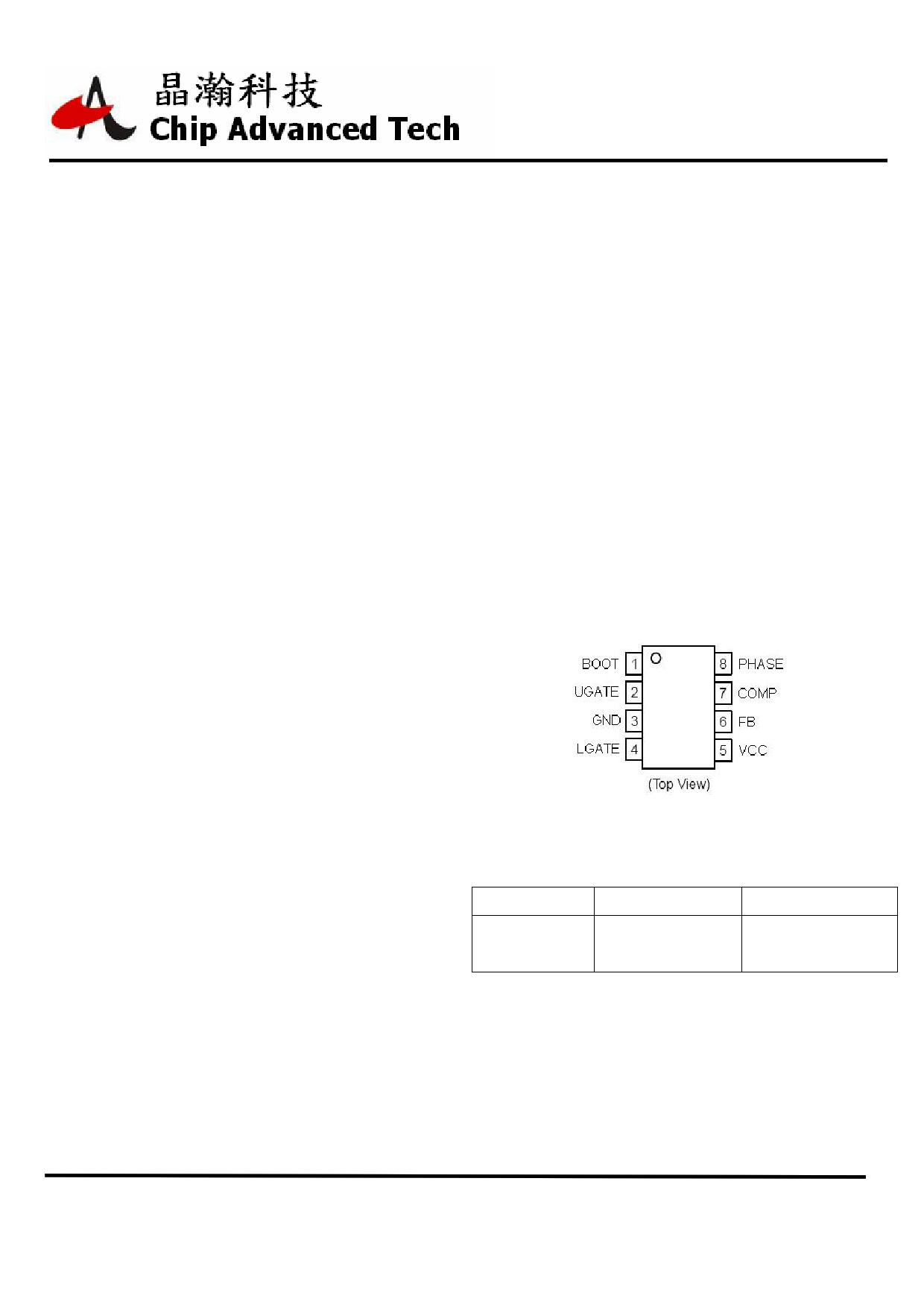
PIN CONFIGURATION:
ORDERING INFORMATION:
Part Number
CAT7580CA
CAT7580CH
Package
8L SOP(Green)
8L SOP(Pb-free)
Shipping
2500/Tape & Reel
12/14/2005
Rev. 1.1
1 www.chipadvanced.com
Free Datasheet http://www.Datasheet4U.com
1 page 
CAT7580
FUNCTION DESCRIPTION
VOUT UVLO
Duty Cycle and Maximum Pulse Width Limits
In steady state DC operation, the duty cycle will
stabilize at an operating point defined by the
ratio of the input to the output voltage. The
CAT7580 can achieve a 90% duty cycle. There
is a built in off−time which ensures that the
bootstrap supply is charged every cycle.
INPUT VOLTAGE RANGE (VCC AND BOOT)
The input voltage range for both VCC and
BOOT is 4.5 V to 13.2 V with respect to GND
and PHASE, respectively. Although BOOT is
rated at 13.2 V with respect to PHASE, it can
also tolerate 26.5 V with respect to GND.
NORMAL SHUTDOWN BEHAVIOR
Normal shutdown occurs when the IC stops
witching because the input supply reaches
UVLO threshold. In this case, switching stops,
the internal SS is discharged, and all GATE
pins go low. The switch node enters a high
impedance state and the output capacitors
discharge through the load with no ringing on
the output voltage.
INTERNAL SOFT−START
The CAT7580 features an internal soft−start
function, which reduces inrush current and
overshoot of the output voltage. Soft−start is
achieved by ramping up the internal soft−start
voltage (VSS) which is applied to the input of
the error amplifier. This sequence begins once
VCC surpasses its UVLO threshold. The typical
soft−start time is 1.2 msec. The internal
soft−start voltage is held low when the part is in
UVLO.
VCC UVLO
Undervoltage Lockout (UVLO) is provided to
ensure that unexpected behavior does not
occur when VCC is too low to support the
internal rails and power the converter. For the
CAT7580, the UVLO is set to ensure that the IC
will start up when VCC reaches 4.2 V and
shutdown when VCC drops below 3.7 V. This
permits operation when converting from a 5.0 V
input voltage.
The FB pin is monitored during converter
operation by an Under-Voltage (UV)
comparator. If the FB voltage drops below 75%
of the reference voltage (0.8V), a fault signal is
internally generated, and the fault logic shuts
down the regulator.
THERMAL SHUTDOWN
The CAT7580 also provides Thermal Shutdown
(TSD) for added protection. The TSD circuit
monitors the die temperature and turns off the
top and bottom gate drivers if an over
temperature condition is detected. The internal
soft−start state is reset. This is a latched state
and requires a power cycle to reset.
DRIVERS
The CAT7580 includes 1.5 A gate drivers to
switch external N−Channel MOSFETs. This
allows the CAT7580 to address high−power as
well as low−power conversion requirements.
The gate drivers also include adaptive
non−overlap circuitry. The non−overlap circuitry
increases efficiency, which minimizes power
dissipation, by minimizing the body diode
conduction time.
Careful selection and layout of external
components is required, to realize the full
benefit of the onboard drivers. The capacitors
between VCC and GND and between BOOT
and PHASE must be placed as close as
possible to the IC. The current paths for the
UGATE and LGATE connections must be
optimized. A ground plane should be placed on
the closest layer for return currents to GND in
order to reduce loop area and inductance in the
gate drive circuit.
INPUT CAPACITOR SELECTION
The input capacitor has to sustain the ripple
current produced during the on time of the
upper MOSFET, so it must have a low ESR to
minimize the losses. The RMS value of this
ripple is:
where D is the duty cycle, linRMS is the input
RMS current, and IOUT is the load current. The
equation reaches its maximum value with D =
0.5. Losses in the input capacitors can be
12/14/2005
Rev. 1.1
5 www.chipadvanced.com
Free Datasheet http://www.Datasheet4U.com
5 Page 
CAT7580
CONTACT:
HEADQUARTERS:
8F, No.1, Jin-Shan 7th St., Hsin-Chu,
300 Taiwan, ROC.
Tel: +886-3-666-8301
Fax: +886-3-666-8630
Website: http://www.chipadvanced.com
Information furnished is believed to be accurate and reliable. However, CAT Inc. assumes no
responsibility for the consequences for use of such information or for any infringement of
patens or other rights of third parties which may result from its use. No license is grated by
implication or otherwise under any patent or patent rights of CAT Inc. Specifications
mentioned in this publication are subject to change without notice. This publication
supersedes and replaces all information if previously supplied. CAT Inc. products are not
authorized for use as critical components in life support devices or systems without the
express written approval of CAT Inc.
The CAT logo is a registered trademark of Chip Advanced Technology
2004 Chip Advanced Technology Inc. – All Right Reserved.
12/14/2005
Rev. 1.1
11 www.chipadvanced.com
Free Datasheet http://www.Datasheet4U.com
11 Page | ||
| Páginas | Total 11 Páginas | |
| PDF Descargar | [ Datasheet CAT7580.PDF ] | |
Hoja de datos destacado
| Número de pieza | Descripción | Fabricantes |
| CAT7580 | Synchronous and Rectified Buck PWM Controller | Chip Advanced Tech |
| CAT7581 | Synchronous Single Buck PWM Controller | CAT |
| Número de pieza | Descripción | Fabricantes |
| SLA6805M | High Voltage 3 phase Motor Driver IC. |
Sanken |
| SDC1742 | 12- and 14-Bit Hybrid Synchro / Resolver-to-Digital Converters. |
Analog Devices |
|
DataSheet.es es una pagina web que funciona como un repositorio de manuales o hoja de datos de muchos de los productos más populares, |
| DataSheet.es | 2020 | Privacy Policy | Contacto | Buscar |