|
|
|
PDF IRFB812PBF Data sheet ( Hoja de datos )
| Número de pieza | IRFB812PBF | |
| Descripción | Power MOSFET ( Transistor ) | |
| Fabricantes | International Rectifier | |
| Logotipo | ||
Hay una vista previa y un enlace de descarga de IRFB812PBF (archivo pdf) en la parte inferior de esta página. Total 8 Páginas | ||
|
No Preview Available !
Applications
• Zero Voltage Switching SMPS
• Uninterruptible Power Supplies
• Motor Control applications
PD -97693
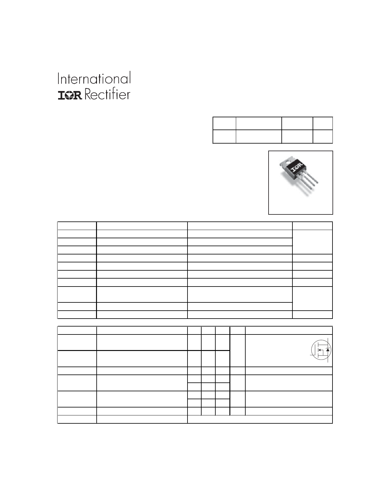
IRFB812PbF
HEXFET® Power MOSFET
VDSS RDS(on) typ. Trr typ. ID
500V 1.75Ω
75ns 3.6A
Features and Benefits
• Fast body diode eliminates the need for external
diodes in ZVS applications.
• Lower Gate charge results in simpler drive requirements.
• Higher Gate voltage threshold offers improved noise
immunity.
TO-220AB
Absolute Maximum Ratings
Parameter
Max.
Units
ID @ TC = 25°C Continuous Drain Current, VGS @ 10V
ID @ TC = 100°C Continuous Drain Current, VGS @ 10V
IDM Pulsed Drain Current
PD @TC = 25°C Power Dissipation
Linear Derating Factor
VGS
dv/dt
Gate-to-Source Voltage
ePeak Diode Recovery dv/dt
TJ
TSTG
Operating Junction and
Storage Temperature Range
Soldering Temperature, for 10 seconds
Mounting torque, 6-32 or M3 screw
Diode Characteristics
3.6
2.3
14.4
78
0.63
± 20
32
-55 to + 150
300 (1.6mm from case )
x x10lb in (1.1N m)
A
W
W/°C
V
V/ns
°C
Symbol
IS
ISM
VSD
trr
Parameter
Continuous Source Current
(Body Diode)
Pulsed Source Current
Ã(Body Diode)
Diode Forward Voltage
Reverse Recovery Time
Qrr Reverse Recovery Charge
IRRM Reverse Recovery Current
ton Forward Turn-On Time
Min. Typ. Max. Units Conditions
––– ––– 3.6
MOSFET symbol
D
A showing the
––– ––– 14.4
integral reverse
G
––– ––– 1.2
p-n junction diode.
S
fV TJ = 25°C, IS = 3.6A, VGS = 0V
––– 75 110
––– 94 140
––– 135 200
––– 220 330
ns TJ = 25°C, IF = 3.6A
fTJ = 125°C, di/dt = 100A/μs
fnC TJ = 25°C, IS = 3.6A, VGS = 0V
fTJ = 125°C, di/dt = 100A/μs
––– 3.2 4.8 A TJ = 25°C
Intrinsic turn-on time is negligible (turn-on is dominated by LS+LD)
Notes through are on page 2
www.irf.com
1
6/23/11
Free Datasheet http://www.datasheetlist.com/
1 page 
4
3
2
1
0
25
50 75 100 125
TC , CaseTemperature (°C)
Fig 9. Maximum Drain Current Vs.
Case Temperature
150
IRFB812PbF
3.0
2.5 VGS = 20V
VGS = 10V
2.0
1.5
01234567
ID , Drain Current (A)
Fig 9. Typical Rdson Vs. Drain Current
10
1 D = 0.50
0.20
0.10
0.1 0.05
0.02
0.01
0.01
0.001
1E-006
SINGLE PULSE
( THERMAL RESPONSE )
Notes:
1. Duty Factor D = t1/t2
2. Peak Tj = P dm x Zthjc + Tc
1E-005
0.0001
0.001
t1 , Rectangular Pulse Duration (sec)
0.01
0.1
Fig 11. Maximum Effective Transient Thermal Impedance, Junction-to-Case
www.irf.com
5
Free Datasheet http://www.datasheetlist.com/
5 Page | ||
| Páginas | Total 8 Páginas | |
| PDF Descargar | [ Datasheet IRFB812PBF.PDF ] | |
Hoja de datos destacado
| Número de pieza | Descripción | Fabricantes |
| IRFB812PBF | Power MOSFET ( Transistor ) | International Rectifier |
| Número de pieza | Descripción | Fabricantes |
| SLA6805M | High Voltage 3 phase Motor Driver IC. |
Sanken |
| SDC1742 | 12- and 14-Bit Hybrid Synchro / Resolver-to-Digital Converters. |
Analog Devices |
|
DataSheet.es es una pagina web que funciona como un repositorio de manuales o hoja de datos de muchos de los productos más populares, |
| DataSheet.es | 2020 | Privacy Policy | Contacto | Buscar |