|
|
|
PDF MBR3045PT Data sheet ( Hoja de datos )
| Número de pieza | MBR3045PT | |
| Descripción | Power Rectifier | |
| Fabricantes | ON Semiconductor | |
| Logotipo | ||
Hay una vista previa y un enlace de descarga de MBR3045PT (archivo pdf) en la parte inferior de esta página. Total 4 Páginas | ||
|
No Preview Available !
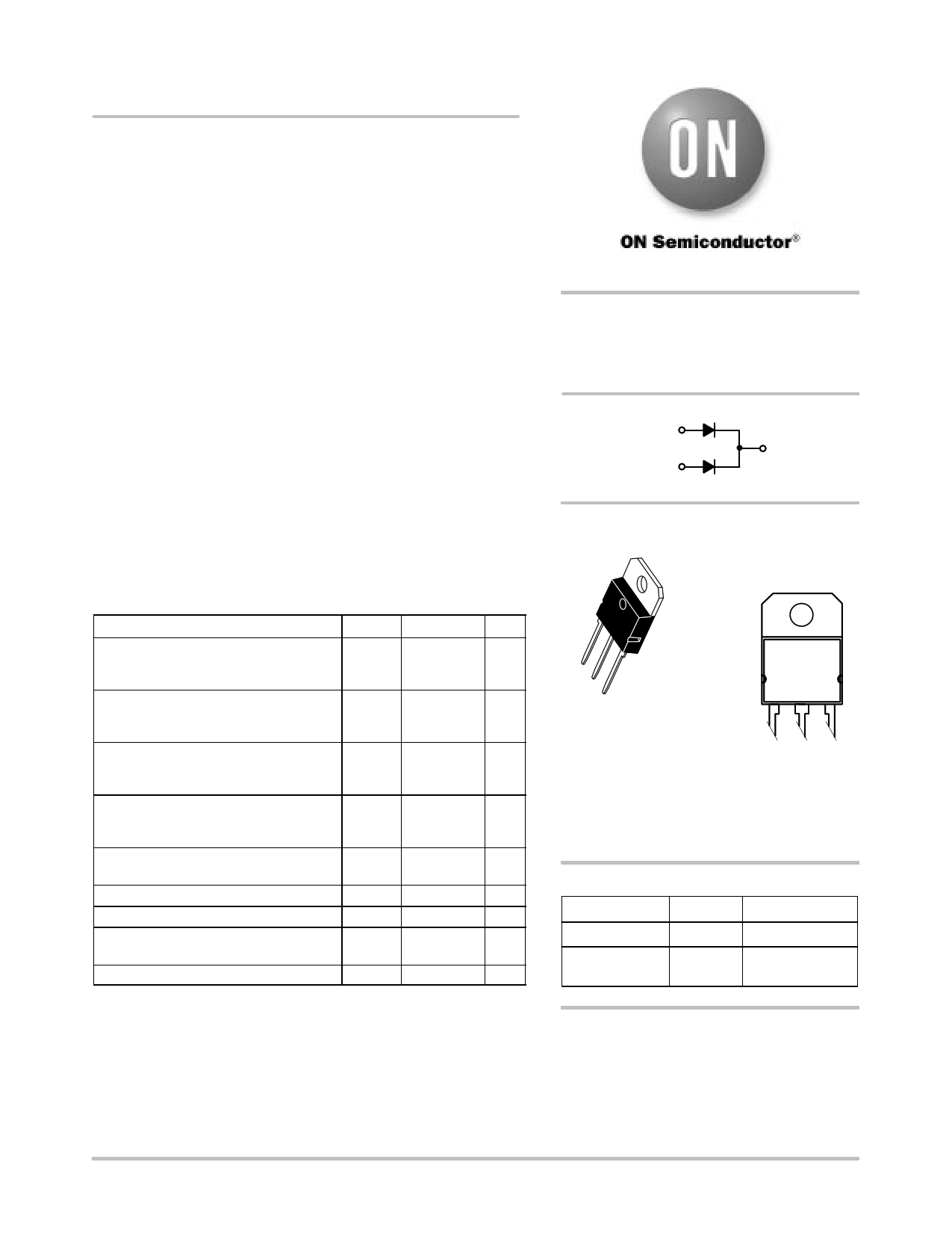
MBR3045PT
Preferred Device
SWITCHMODEt
Power Rectifier
These state−of−the−art devices use the Schottky Barrier principle
with a platinum barrier metal.
Features
• Dual Diode Construction; Terminals 1 and 3 may be Connected for
Parallel Operation at Full Rating
• Guard−ring for Stress Protection
• Low Forward Voltage
• 175°C Operating Junction Temperature
• Pb−Free Package is Available*
Mechanical Characteristics
• Case: Epoxy, Molded
• Weight: 4.3 Grams (Approximately)
• Finish: All External Surfaces Corrosion Resistant and Terminal
Leads are Readily Solderable
• Lead Temperature for Soldering Purposes:
260°C Max. for 10 Seconds
MAXIMUM RATINGS
Rating
Symbol Max Unit
Peak Repetitive Reverse Voltage
Working Peak Reverse Voltage
DC Blocking Voltage
VRRM 45 V
VRWM
VR
Average Rectified Forward Current
IF(AV)
A
(Rated VR, TC = 105°C)
Per Device
30
Per Diode
15
Peak Repetitive Forward Current,
(Rated VR, Square Wave,
20 kHz) Per Diode
IFRM
30 A
Non−Repetitive Peak Surge Current
(Surge Applied at Rated Load Conditions
Halfwave, Single Phase, 60 Hz)
IFSM
200 A
Peak Repetitive Reverse Current (2.0 ms, IRRM 2.0 A
1.0 kHz) Per Diode (See Figure 6)
Storage Temperature Range
Operating Junction Temperature (Note 1)
Peak Surge Junction Temperature
(Forward Current Applied)
Tstg
TJ
TJ(pk)
−65 to +175
−65 to +175
175
°C
°C
°C
Voltage Rate of Change (Rated VR)
dv/dt
10,000 V/ms
Maximum ratings are those values beyond which device damage can occur.
Maximum ratings applied to the device are individual stress limit values (not
normal operating conditions) and are not valid simultaneously. If these limits are
exceeded, device functional operation is not implied, damage may occur and
reliability may be affected.
1. The heat generated must be less than the thermal conductivity from
Junction−to−Ambient: dPD/dTJ < 1/RqJA.
*For additional information on our Pb−Free strategy and soldering details, please
download the ON Semiconductor Soldering and Mounting Techniques
Reference Manual, SOLDERRM/D.
© Semiconductor Components Industries, LLC, 2006
February, 2006 − Rev. 3
1
http://onsemi.com
SCHOTTKY BARRIER
RECTIFIER
30 AMPERES, 45 VOLTS
12
34
MARKING
DIAGRAM
4
1
2
3
SOT−93
CASE 340D
PLASTIC
AYWWG
MBR3045PT
A = Assembly Location
Y = Year
WW = Work Week
G = Pb−Free Package
ORDERING INFORMATION
Device
Package
Shipping
MBR3045PT
SOT−93 30 Units / Rail
MBR3045PTG
SOT−93
(Pb−Free)
30 Units / Rail
Preferred devices are recommended choices for future use
and best overall value.
Publication Order Number:
MBR3045PT/D
Free Datasheet http://www.datasheet4u.com/
1 page | ||
| Páginas | Total 4 Páginas | |
| PDF Descargar | [ Datasheet MBR3045PT.PDF ] | |
Hoja de datos destacado
| Número de pieza | Descripción | Fabricantes |
| MBR3045PT | Schottky Barrier Rectifier ( Diode ) | Inchange Semiconductor |
| MBR3045PT | 30 Ampere Schottky Barrier Rectifiers | Fairchild Semiconductor |
| MBR3045PT | 30A SCHOTTKY BARRIER RECTIFIER | Diodes Incorporated |
| MBR3045PT | SURFACE MOUNT SCHOTTKY BARRIER RECTIFIER | MIC |
| Número de pieza | Descripción | Fabricantes |
| SLA6805M | High Voltage 3 phase Motor Driver IC. |
Sanken |
| SDC1742 | 12- and 14-Bit Hybrid Synchro / Resolver-to-Digital Converters. |
Analog Devices |
|
DataSheet.es es una pagina web que funciona como un repositorio de manuales o hoja de datos de muchos de los productos más populares, |
| DataSheet.es | 2020 | Privacy Policy | Contacto | Buscar |