|
|
|
PDF PE84244 Data sheet ( Hoja de datos )
| Número de pieza | PE84244 | |
| Descripción | SPDT MOSFET RF SWITCH | |
| Fabricantes | Peregrine Semiconductor | |
| Logotipo | ||
Hay una vista previa y un enlace de descarga de PE84244 (archivo pdf) en la parte inferior de esta página. Total 6 Páginas | ||
|
No Preview Available !
Product Description
The PE84244 MOSFET RF Switch is designed to cover a
broad range of applications from DC to 3.0 GHz. This switch
integrates on-board CMOS control logic with a low voltage
CMOS compatible control input. Using a +3-volt nominal
power supply voltage, a 1 dB compression point of +27 dBm
can be achieved. The PE84244 also exhibits excellent
isolation of 28 dB at 2.0 GHz and is offered in a small 8-lead
MSOP package.
The PE4244 MOSFET RF Switch is manufactured in
Peregrine’s patented Ultra Thin Silicon (UTSi) CMOS
process, offering the performance of GaAs with the economy
and integration of conventional CMOS.
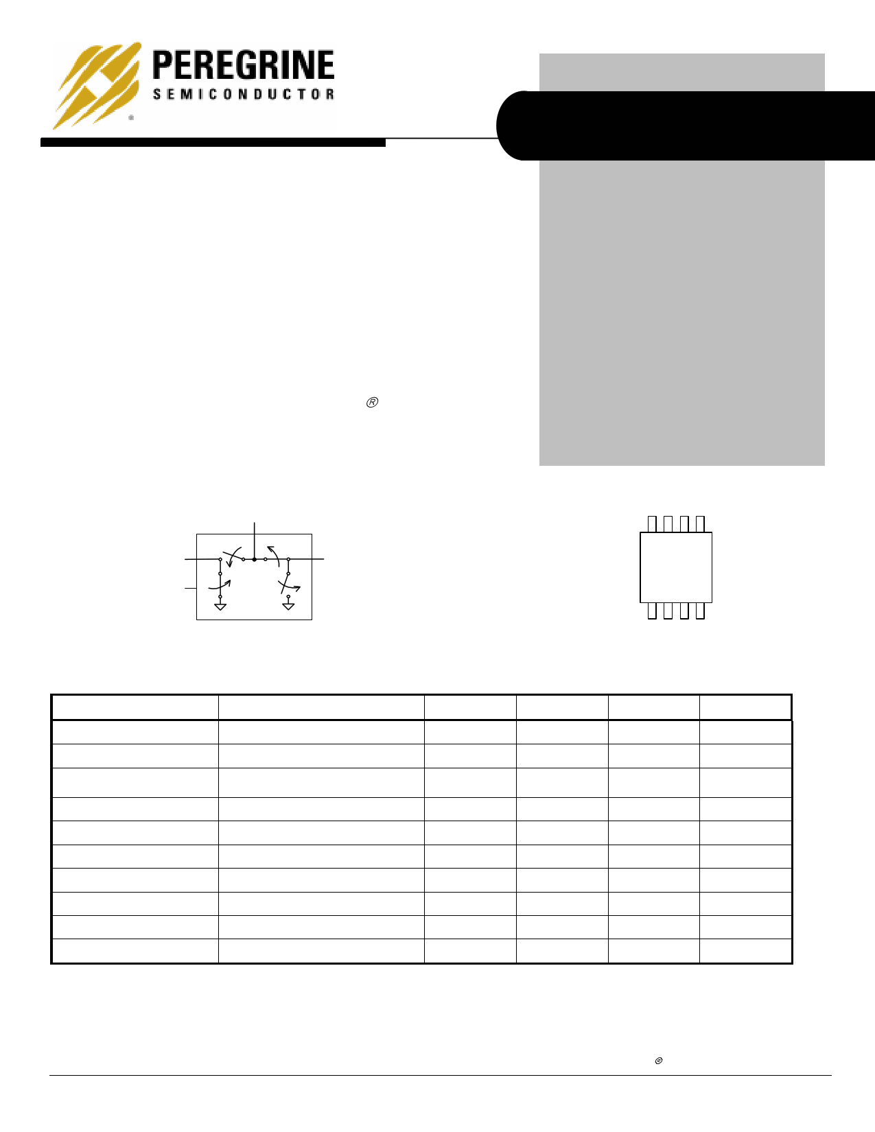
Figure 1. Functional Schematic Diagram
RFCommon
RF1
CTRL
RF2
PRELIMINARY SPECIFICATION
PE84244
Military Operating Temperature Range
SPDT MOSFET RF Switch
Features
• Single +3.0-volt Power Supply
• Low Insertion loss: 0.70 dB up
to 2.0 GHz
• High isolation of 39 dB at 1.0
GHz, 28 dB at 2.0 GHz, typical
• Typical 1 dB compression of
+27 dBm
• Single-pin CMOS logic control
• Packaged in 8-lead MSOP
Figure 2. Package Type
8-lead
MSOP
Table 1. Electrical Specifications -55 °C to +125 °C, VDD = 3 V (ZS = ZL = 50 Ω)
Parameter
Conditions
Minimum
Typical
Maximum
Units
Operation Frequency1
DC
3000
MHz
Insertion Loss
Isolation – RFCommon to
RF1/RF2
Isolation – RF1 to RF2
2000 MHz
2000 MHz
2000 MHz
0.7 0.95 dB
25 28
dB
24 27
dB
Return Loss
2000 MHz
18 25
dB
‘ON’ Switching Time
CTRL to 0.1 dB final value, 2 GHz
200
ns
‘OFF’ Switching Time
CTRL to 25 dB isolation, 2 GHz
90
ns
Video Feedthrough2
15 mVpp
Input 1 dB Compression
2000 MHz
25 27
dBm
Input IP3
2000 MHz, 14dBm
40 42
dBm
Notes: 1. Device linearity will begin to degrade below 10 MHz.
2. The DC transient at the output of any port of the switch when the control voltage is switched from Low to High or High to Low in a
50 Ω test set-up, measured with 1ns risetime pulses and 500 MHz bandwidth.
PEREGRINE SEMICONDUCTOR CORP. | http://www.peregrine-semi.com
Copyright Peregrine Semiconductor Corp. 2003
Page 1 of 7
Free Datasheet http://www.datasheet4u.com/
1 page 
PE84244
Preliminary Specification
Evaluation Kit Information
Evaluation Kit
The SPDT Switch Evaluation Kit board was
designed to ease customer evaluation of the
PE84244 SPDT switch. The RF common port is
connected through a 50Ω transmission line to the
top left SMA connector, J1. Port 1 and Port 2 are
connected through 50Ω transmission lines to the
top two SMA connectors on the right side of the
board, J3 and J4. A through transmission line
connects SMA connectors J6 and J8. This
transmission line can be used to estimate the loss
of the PCB over the environmental conditions
being evaluated.
The board is constructed of a two metal layer FR4
material with a total thickness of 0.031”. The
bottom layer provides ground for the RF
transmission lines. The transmission lines were
designed using a coplanar waveguide with ground
plane model using a trace width of 0.030”, trace
gaps of 0.007”, dielectric thickness of 0.028”,
metal thickness of 0.0014” and εr of 4.4.
J2 provides a means for controlling DC and digital
inputs to the device. Starting from the lower left
pin, the second pin to the right (J2-3) is connected
to the device CNTL input. The fourth pin to the
right (J2-7) is connected to the device VDD input.
A decoupling capacitor (100 pF) is provided on
both CNTL and VDD traces. It is the responsibility
of the customer to determine proper supply
decoupling for their design application. Removing
these components from the evaluation board has
not been shown to degrade RF performance.
Figure 12. Evaluation Board Layouts
Figure 13. Evaluation Board Schematic
J2-7
100 pF
Optional
J2-3
100 pF
Optional
VDD
CNTL
GND
RFC
J1
RF1
GND
GND
RF2
J6 J8
J3
J4
PEREGRINE SEMICONDUCTOR CORP. | http://www.peregrine-semi.com
Copyright Peregrine Semiconductor Corp. 2003
Page 5 of 7
Free Datasheet http://www.datasheet4u.com/
5 Page | ||
| Páginas | Total 6 Páginas | |
| PDF Descargar | [ Datasheet PE84244.PDF ] | |
Hoja de datos destacado
| Número de pieza | Descripción | Fabricantes |
| PE84244 | SPDT MOSFET RF SWITCH | Peregrine Semiconductor |
| Número de pieza | Descripción | Fabricantes |
| SLA6805M | High Voltage 3 phase Motor Driver IC. |
Sanken |
| SDC1742 | 12- and 14-Bit Hybrid Synchro / Resolver-to-Digital Converters. |
Analog Devices |
|
DataSheet.es es una pagina web que funciona como un repositorio de manuales o hoja de datos de muchos de los productos más populares, |
| DataSheet.es | 2020 | Privacy Policy | Contacto | Buscar |