|
|
|
PDF TC670 Data sheet ( Hoja de datos )
| Número de pieza | TC670 | |
| Descripción | Tiny Predictive Fan Failure Detector | |
| Fabricantes | Microchip | |
| Logotipo | ||
Hay una vista previa y un enlace de descarga de TC670 (archivo pdf) en la parte inferior de esta página. Total 12 Páginas | ||
|
No Preview Available !
TC670
Tiny Predictive Fan Failure Detector
Features
• Fan Wear-out Detection for 2-Wire Linear
Controlled Fans
• Replacement System for 3-Wire Fans
• Fan Alert Signal when Fan Speed is below
Programmed Threshold
• CLEAR Capability for Eliminating False Alarm
• Low Operating Current, 90µA (typ.)
• VDD Range 3.0V to 5.5V
• Available in a 6-Pin SOT-23 Package
Applications
• Protection for Linear Controlled Fans
• Power Supplies
• Industrial Equipment
• PCs and Notebooks
• Data Storage
• Data Communications Equipment
• Instrumentation
Device Selection Table
Part Number Package
TC670ECH 6-Pin SOT-23
Temp. Range
-40°C to +85°C
Package Type
SOT-23A-6
THRESHOLD 1
GND 2
CLEAR 3
6 SENSE
5 ALERT
4 VDD
General Description
The TC670 is an integrated fan speed sensor that
predicts and/or detects fan failure, preventing thermal
damage to systems with cooling fans. When the fan
speed falls below a user specified level, the TC670
asserts an ALERT signal. With this design, a critical
minimum fan speed is determined by the user. The fan
alert level is then set with a resistor divider on the
THRESHOLD pin (Pin 1) of the TC670. When the
minimum fan speed is reached, the ALERT pin (Pin 5)
changes from a digital HIGH to LOW. This failure
detection works with all linear controlled 2-wire fans.
The TC670 eliminates the need for 3-wire fan solutions.
A CLEAR option can be used to reset the ALERT signal,
allowing the flexibility of connecting the ALERT output
of the TC670 with other Alert/FAULT interrupts in the
system. This feature can be implemented so that false
Fan Fault conditions do not initiate system shutdown.
The TC670 is specified to operate over the full
industrial temperature range of -40°C to +85°C. The
TC670 is offered in a SOT23-6 pin package and
consumes 90µA (typ) during operation. The space
saving package and low power consumption make this
device an ideal choice for systems requiring fan speed
monitoring.
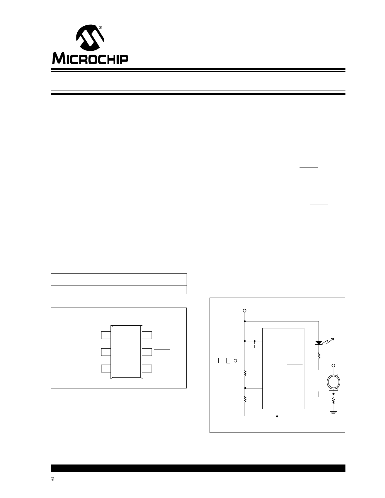
Typical Application Circuit
+5V
4 VDD
ALERT
LED
0.1 µF
3 CLEAR
From
R3
Microcontroller
ALERT 5
R4
+12V
DC
1
THRESHOLD
SENSE 6
CSENSE
FAN
R2
GND
RSENSE
2
© 2002 Microchip Technology Inc.
DS21688B-page 1
Free Datasheet http://www.datasheet4u.com/
1 page 
4.0 DETAILED DESCRIPTION
The TC670 is an integrated fan speed sensor that
predicts/detects fan failure, consequently preventing
thermal damage to systems with cooling fans. When
the fan speed falls below a user programmed threshold
level, the TC670 asserts an ALERT signal. This
threshold is set with an external resistor divider
network.
FIGURE 4-1:
TC670 BLOCK DIAGRAM
VDD
THRESHOLD
Logic
CLEAR
ALERT
GND
Frequency to
Voltage
Bandgap Oscillator
SENSE
50kΩ
124mV
As shown in Figure 4-1, the TC670 senses the fan
pulses and internally converts those pulses from a
frequency into an analog voltage. This voltage is then
compared with a DC voltage present on the THRESH-
OLD pin. If the converted frequency-to-voltage value
from the fan’s pulses falls below the THRESHOLD
voltage, a FAULT signal is asserted through the ALERT
pin (active LOW).
In a 3.0V system, the external fan alert level on the
THRESHOLD pin can be designed from 0.0V (stalled
fan) and up to 2.4V (for 13,000 RPM) to cover most of
the common fan speeds. This failure detection system
works with linear controlled 2-wire fans and eliminates
the need for 3-wire fans. The TC670 can work with 3-
wire fans as well either by using the SENSE circuit or
by directly sensing the RPM output from the 3rd wire.
A CLEAR pin is provided to allow the user to reset the
ALERT pin status back to a HIGH state. This CLEAR
option also allows the flexibility of connecting the
ALERT output of the TC670 with other Alert/FAULT
interrupts in the system without having a risk of a
system shutdown due to false Fan Fault condition.
TC670
FIGURE 4-2:
VDD = +5V
TYPICAL APPLICATION
CIRCUIT
4 VDD
ALERT
LED
0.1 µF
3 CLEAR
From
Microcontroller
R3
5
ALERT
R4
+12V
DC
Vthreshold
1
THRESHOLD
SENSE
6
CSENSE
FAN
R2
GND
RSENSE
2
VTHRESHOLD = VDDR-----2---R--+--2---R----3--
Note: This typical application circuit uses an LED to indicate that a
fan failure has occurred.
4.1 SENSE Input
As shown in Figure 4-2, the SENSE input (Pin 6) is
connected through a sensing capacitor (CSENSE). A
low value current sensing resistor (RSENSE) is also
connected to the low side of the fan to the ground return
leg of the fan. During normal fan operation, commuta-
tion occurs as each pole of the fan is energized. This
causes brief interruptions in the fan current, seen as
pulses across the sense resistor.
These short rapid changes in fan current cause a
corresponding dV/dt voltage across the sense resistor
as well as a corresponding dI/dt current across the
sense capacitor. The current across CSENSE is termi-
nated with the internal 50kΩ input resistance at the
SENSE pin of the TC670. When positive going fan
pulses at the SENSE input are greater than 124mV
(typ) the TC670 latches in those voltage spikes. This
124mV (typ) SENSE input built-in threshold reduces
false triggering errors caused by extraneous noise
pulses associated with a running fan. The presence
and frequency of these pulses is a direct indication of
fan operation and fan speed.
© 2002 Microchip Technology Inc.
DS21688B-page 5
Free Datasheet http://www.datasheet4u.com/
5 Page 
TC670
Information contained in this publication regarding device
applications and the like is intended through suggestion only
and may be superseded by updates. It is your responsibility to
ensure that your application meets with your specifications.
No representation or warranty is given and no liability is
assumed by Microchip Technology Incorporated with respect
to the accuracy or use of such information, or infringement of
patents or other intellectual property rights arising from such
use or otherwise. Use of Microchip’s products as critical com-
ponents in life support systems is not authorized except with
express written approval by Microchip. No licenses are con-
veyed, implicitly or otherwise, under any intellectual property
rights.
Trademarks
The Microchip name and logo, the Microchip logo, FilterLab,
KEELOQ, microID, MPLAB, PIC, PICmicro, PICMASTER,
PICSTART, PRO MATE, SEEVAL and The Embedded Control
Solutions Company are registered trademarks of Microchip Tech-
nology Incorporated in the U.S.A. and other countries.
dsPIC, ECONOMONITOR, FanSense, FlexROM, fuzzyLAB,
In-Circuit Serial Programming, ICSP, ICEPIC, microPort,
Migratable Memory, MPASM, MPLIB, MPLINK, MPSIM,
MXDEV, PICC, PICDEM, PICDEM.net, rfPIC, Select Mode
and Total Endurance are trademarks of Microchip Technology
Incorporated in the U.S.A.
Serialized Quick Turn Programming (SQTP) is a service mark
of Microchip Technology Incorporated in the U.S.A.
All other trademarks mentioned herein are property of their
respective companies.
© 2002, Microchip Technology Incorporated, Printed in the
U.S.A., All Rights Reserved.
Printed on recycled paper.
© 2002 Microchip Technology Inc.
Microchip received QS-9000 quality system
certification for its worldwide headquarters,
design and wafer fabrication facilities in
Chandler and Tempe, Arizona in July 1999
and Mountain View, California in March 2002.
The Company’s quality system processes and
procedures are QS-9000 compliant for its
PICmicro® 8-bit MCUs, KEELOQ® code hopping
devices, Serial EEPROMs, microperipherals,
non-volatile memory and analog products. In
addition, Microchip’s quality system for the
design and manufacture of development
systems is ISO 9001 certified.
DS21688B-page 11
Free Datasheet http://www.datasheet4u.com/
11 Page | ||
| Páginas | Total 12 Páginas | |
| PDF Descargar | [ Datasheet TC670.PDF ] | |
Hoja de datos destacado
| Número de pieza | Descripción | Fabricantes |
| TC670 | Tiny Predictive Fan Failure Detector | Microchip |
| Número de pieza | Descripción | Fabricantes |
| SLA6805M | High Voltage 3 phase Motor Driver IC. |
Sanken |
| SDC1742 | 12- and 14-Bit Hybrid Synchro / Resolver-to-Digital Converters. |
Analog Devices |
|
DataSheet.es es una pagina web que funciona como un repositorio de manuales o hoja de datos de muchos de los productos más populares, |
| DataSheet.es | 2020 | Privacy Policy | Contacto | Buscar |