|
|
|
PDF S10113 Data sheet ( Hoja de datos )
| Número de pieza | S10113 | |
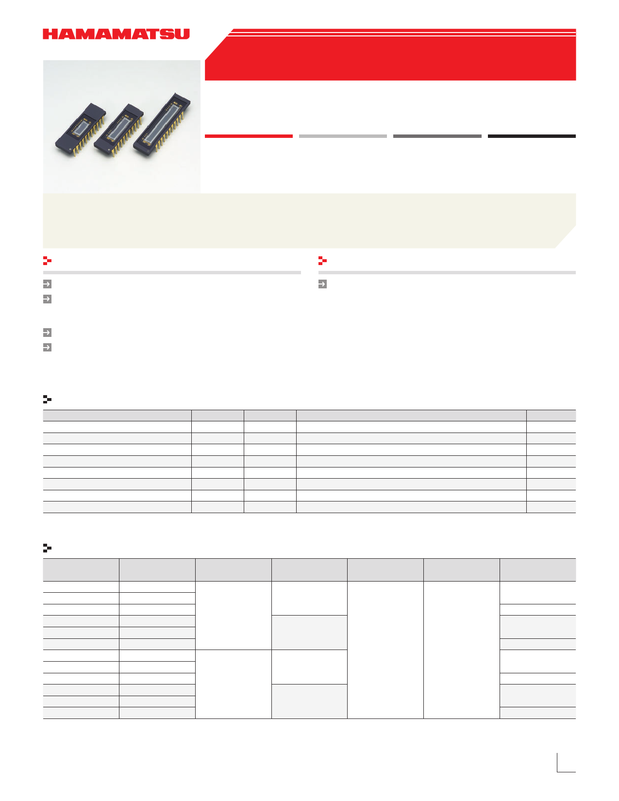
| Descripción | (S10111 - S10114) Current-output type sensors | |
| Fabricantes | Hamamatsu | |
| Logotipo | ||
Hay una vista previa y un enlace de descarga de S10113 (archivo pdf) en la parte inferior de esta página. Total 11 Páginas | ||
|
No Preview Available !
CMOS linear image sensors
S10111 to S10114 series
Current-output type sensors with
variable integration time function
The S10111 to S10114 series are self-scanning photodiode arrays designed speci¿cally as detectors for spectroscopy. The scan-
ning circuit operates at low power consumption and is easy to handle. Each photodiode has a large active area with high UV sen-
sitivity.
Features
Variable integration time for each pixel
Wide active area
Pixel pitch: 50 m, 25 m
Pixel height: 2.5 mm, 0.5 mm
High UV sensitivity
Large saturation output charge
Applications
Spectrophotometry
Absolute maximum ratings
Parameter
Supply voltage
Clock pulse voltage
Start pulse voltage
Integration time control pulse
OverÀow gate voltage
OverÀow drain voltage
Operating temperature*1
Storage temperature*1
*1: No condensation
Symbol
Vdd
V(CLK)
V(ST)
V(INT)
Vofg
Vofd
Topr
Tstg
Condition
Ta=25 °C
Ta=25 °C
Ta=25 °C
Ta=25 °C
Ta=25 °C
Ta=25 °C
www.DataSheet.net/
Shape speci¿cations
Type no.
S10111-128Q
S10111-256Q
S10111-512Q
S10112-128Q
S10112-256Q
S10112-512Q
S10113-256Q
S10113-512Q
S10113-1024Q
S10114-256Q
S10114-512Q
S10114-1024Q
Number of pixels
128
256
512
128
256
512
256
512
1024
256
512
1024
Pixel pitch
(m)
50
25
Pixel height
(mm)
2.5
0.5
0.5
2.5
Value
-0.3 to +6
-0.3 to +6
-0.3 to +6
-0.3 to +6
-0.3 to +6
-0.3 to +6
-5 to +65
-10 to +85
Unit
V
V
V
V
V
V
°C
°C
Package
Window material
Ceramic
Quartz
(t=0.5 mm)
Weight
(g)
3.0
3.5
3.0
3.5
3.0
3.5
3.0
3.5
www.hamamatsu.com
1
Datasheet pdf - http://www.DataSheet4U.co.kr/
1 page 
CMOS linear image sensors
S10111 to S10114 series
Timing chart
CLK
ST
tpi(ST), integration time
INT
Active Video
(available term)
EOS
1st 2nd 3rd 4th
Enlarged view
tf(CLK)
tr(CLK)
Last pixel
CLK
1/f(CLK)
tr(ST)
tf(ST)
1st 2nd 3rd 4th
ST t(ST-CLK)
INT
t(CLK-ST)
t(INT-CLK)
tr(INT)
t(CLK-INT)
INT should be "high" when not reading pixels.
tf(INT)
Active Video (available term)
1st
2nd
3rd
4th 5th
Allow CLK pulse transition from “high” to “low” only one time while ST pulse is “high”.
Integration time is determined by the interval between start pulses.www.DataSheet.net/
Only the switching noise component is output from the Dummy Video line.
Do not use the Dummy Video output during integration readout.
The INT signal is not needed between EOS and the rising edge of the next ST signal.
KMPDC0249ED
Parameter
S1011*-128
Start pulse (ST) interval
S1011*-256
S1011*-512
S1011*-1024
INT pulse rise and fall times
INT pulse - clock pulse timing
Clock pulse - INT pulse timing
Start pulse rise and fall times
Clock pulse duty ratio
Clock pulse rise and fall times
Clock pulse - start pulse timing
Start pulse - clock pulse timing
Symbol
tpi(ST)
tr(INT), tf(INT)
t(INT-CLK)
t(CLK-INT)
tf(ST), tr(ST)
-
tf(CLK), tr(CLK)
t(CLK-ST)
T(ST-CLK)
Min.
130/f(CLK)
258/f(CLK)
514/f(CLK)
1026/f(CLK)
0
30
30
0
40
0
20
20
Typ.
Max.
Unit
--
-
-
-
-
s
--
20 30 ns
-
1 / [2 × f(CLK)]
ns
-
1 / [2 × f(CLK)]
ns
20 30 ns
50 60 %
20 30 ns
- - ns
- - ns
5
Datasheet pdf - http://www.DataSheet4U.co.kr/
5 Page 
CMOS linear image sensors
S10111 to S10114 series
Pin connection
Index mark
ST
INT
Vofg
Vdd
GND
GND
Vdd
Vofd
Active Video
Dummy Video
GND
1
2
3
4
5
6
7
8
9
10
11
22 CLK
21 NC
20 NC
19 NC
18 NC
17 NC
16 NC
15 NC
14 NC
13 NC
12 EOS
KMPDC0230EC
Pin no.
1
2
3
4
5
6
7
8
9
10
11
12
13
14
15
16
17
18
19
20
21
22
Symbol
ST
INT
Vofg
Vdd
GND
GND
Vdd
Vofd
Active Video
Dummy Video
GND
EOS
NC
NC
NC
NC
NC
NC
NC
NC
NC
CLK
Name of pin
Start pulse
Integration time control pulse
OverÀow gate voltage
Supply voltage
Ground
Ground
Supply voltage
OverÀow drain voltage
Video output
Dummy video output
Ground
End of scan
No connection
Clock pulse
I/O
Input
Input
Input
Input
Input
Input
Input
Input
Output
Output
Input
Output
Input
Precautions during use
(1) Electrostatic countermeasures
www.DataSheet.net/
This device has a built-in protection circuit against static electrical charges. However, to prevent destroying the device with electrostatic
charges, take countermeasures such as grounding yourself, the workbench and tools to prevent static discharges. Also protect this de-
vice from surge voltages which might be caused by peripheral equipment.
(2) Incident window
If dust or dirt gets on the light incident window, it will show up as black blemishes on the image. When cleaning, avoid rubbing the
window surface with dry cloth or dry cotton swab, since doing so may generate static electricity. Use soft cloth, paper or a cotton swab
moistened with alcohol to wipe dust and dirt off the window surface. Then blow compressed air onto the window surface so that no spot
or stain remains.
(3) Soldering
To prevent damaging the device during soldering, take precautions to prevent excessive soldering temperatures and times. Soldering
should be performed within 5 seconds at a soldering temperature below 260 °C.
Information furnished by HAMAMATSU is believed to be reliable. However, no responsibility is assumed for possible inaccuracies or omissions.
Specifications are subject to change without notice. No patent rights are granted to any of the circuits described herein.
Type numbers of products listed in the specification sheets or supplied as samples may have a suffix “(X)” which means tentative specifications or a suffix “(Z)”
which means developmental specifications. ©2010 Hamamatsu Photonics K.K.
www.hamamatsu.com
HAMAMATSU PHOTONICS K.K., Solid State Division
1126-1 Ichino-cho, Higashi-ku, Hamamatsu City, 435-8558 Japan, Telephone: (81) 53-434-3311, Fax: (81) 53-434-5184
U.S.A.: Hamamatsu Corporation: 360 Foothill Road, P.O.Box 6910, Bridgewater, N.J. 08807-0910, U.S.A., Telephone: (1) 908-231-0960, Fax: (1) 908-231-1218
Germany: Hamamatsu Photonics Deutschland GmbH: Arzbergerstr. 10, D-82211 Herrsching am Ammersee, Germany, Telephone: (49) 8152-375-0, Fax: (49) 8152-265-8
France: Hamamatsu Photonics France S.A.R.L.: 19, Rue du Saule Trapu, Parc du Moulin de Massy, 91882 Massy Cedex, France, Telephone: 33-(1) 69 53 71 00, Fax: 33-(1) 69 53 71 10
United Kingdom: Hamamatsu Photonics UK Limited: 2 Howard Court, 10 Tewin Road, Welwyn Garden City, Hertfordshire AL7 1BW, United Kingdom, Telephone: (44) 1707-294888, Fax: (44) 1707-325777
North Europe: Hamamatsu Photonics Norden AB: Smidesvägen 12, SE-171 41 Solna, Sweden, Telephone: (46) 8-509-031-00, Fax: (46) 8-509-031-01
Italy: Hamamatsu Photonics Italia S.R.L.: Strada della Moia, 1 int. 6, 20020 Arese, (Milano), Italy, Telephone: (39) 02-935-81-733, Fax: (39) 02-935-81-741
Cat. No. KMPD1090E07 Oct. 2010 DN
11
Datasheet pdf - http://www.DataSheet4U.co.kr/
11 Page | ||
| Páginas | Total 11 Páginas | |
| PDF Descargar | [ Datasheet S10113.PDF ] | |
Hoja de datos destacado
| Número de pieza | Descripción | Fabricantes |
| S10111 | (S10111 - S10114) Current-output type sensors | Hamamatsu |
| S10112 | (S10111 - S10114) Current-output type sensors | Hamamatsu |
| S10113 | (S10111 - S10114) Current-output type sensors | Hamamatsu |
| S10114 | (S10111 - S10114) Current-output type sensors | Hamamatsu |
| Número de pieza | Descripción | Fabricantes |
| SLA6805M | High Voltage 3 phase Motor Driver IC. |
Sanken |
| SDC1742 | 12- and 14-Bit Hybrid Synchro / Resolver-to-Digital Converters. |
Analog Devices |
|
DataSheet.es es una pagina web que funciona como un repositorio de manuales o hoja de datos de muchos de los productos más populares, |
| DataSheet.es | 2020 | Privacy Policy | Contacto | Buscar |