|
|
|
PDF FM22LD16 Data sheet ( Hoja de datos )
| Número de pieza | FM22LD16 | |
| Descripción | 4Mbit F-RAM Memory | |
| Fabricantes | Ramtron | |
| Logotipo | ||
Hay una vista previa y un enlace de descarga de FM22LD16 (archivo pdf) en la parte inferior de esta página. Total 14 Páginas | ||
|
No Preview Available !
www.DataSheet.co.kr
Pre-Production
FM22LD16
4Mbit F-RAM Memory
Features
4Mbit Ferroelectric Nonvolatile RAM
• Organized as 256Kx16
• Configurable as 512Kx8 Using /UB, /LB
• 1014 Read/Write Cycles
• NoDelay™ Writes
• Page Mode Operation to 40MHz
• Advanced High-Reliability Ferroelectric Process
SRAM Compatible
• JEDEC 256Kx16 SRAM Pinout
• 55 ns Access Time, 110 ns Cycle Time
Advanced Features
• Software Programmable Block Write Protect
Description
The FM22LD16 is a 256Kx16 nonvolatile memory
that reads and writes like a standard SRAM. A
ferroelectric random access memory or F-RAM is
nonvolatile, which means that data is retained after
power is removed. It provides data retention for over
10 years while eliminating the reliability concerns,
functional disadvantages, and system design
complexities of battery-backed SRAM (BBSRAM).
Fast write timing and high write endurance make the
F-RAM superior to other types of memory.
In-system operation of the FM22LD16 is very similar
to other RAM devices and can be used as a drop-in
replacement for standard SRAM. Read and write
cycles may be triggered by /CE or simply by
changing the address. The F-RAM memory is
nonvolatile due to its unique ferroelectric memory
process. These features make the FM22LD16 ideal
for nonvolatile memory applications requiring
frequent or rapid writes in the form of an SRAM.
The FM22LD16 includes a low voltage monitor that
blocks access to the memory array when VDD drops
below VDD min. The memory is protected against an
inadvertent access and data corruption under this
condition. The device also features software-
controlled write protection. The memory array is
divided into 8 uniform blocks, each of which can be
individually write protected.
Superior to Battery-backed SRAM Modules
• No Battery Concerns
• Monolithic Reliability
• True Surface Mount Solution, No Rework Steps
• Superior for Moisture, Shock, and Vibration
Low Power Operation
• 2.7V – 3.6V Power Supply
• Low Standby Current (90µA typ.)
• Low Active Current (8 mA typ.)
Industry Standard Configuration
• Industrial Temperature -40° C to +85° C
• 48-ball “Green”/RoHS FBGA package
• Pin compatible with FM21LD16 (2Mb) and
FM23MLD16 (8Mb)
The device is available in a 48-ball FBGA package.
Device specifications are guaranteed over industrial
temperature range –40°C to +85°C.
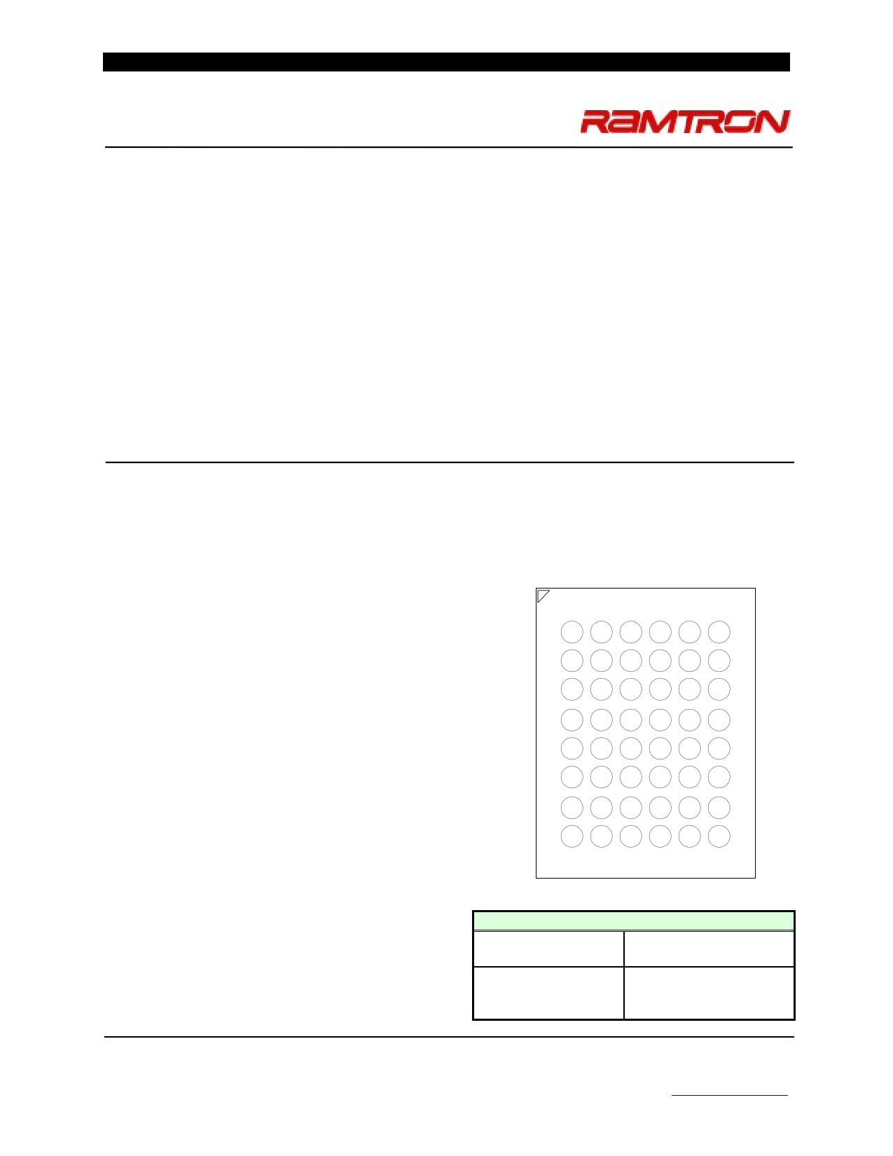
Pin Configuration
1 2 34 5 6
A /LB /OE A0 A1 A2 NC
B
DQ8 /UB
A3
A4 /CE DQ0
C
DQ9 DQ10 A5
A6 DQ1 DQ2
D VSS DQ11 A17 A7 DQ3 VDD
E VDD DQ12 NC A16 DQ4 VSS
F DQ14 DQ13 A14 A15 DQ5 DQ6
G DQ15 NC A12 A13 /WE DQ7
H NC A8 A9 A10 A11 NC
Top View (Ball Down)
Ordering Information
FM22LD16-55-BG 55 ns access, 48-ball
“Green”/RoHS FBGA
FM22LD16-55-BGTR 55 ns access, 48-ball
“Green”/RoHS FBGA,
Tape & Reel
This is a product in the pre-production phase of development. Device
characterization is complete and Ramtron does not expect to change the
specifications. Ramtron will issue a Product Change Notice if any
specification changes are made.
Rev. 2.0
Dec. 2009
Ramtron International Corporation
1850 Ramtron Drive, Colorado Springs, CO 80921
(800) 545-FRAM, (719) 481-7000
http://www.ramtron.com
Page 1 of 14
Datasheet pdf - http://www.DataSheet4U.net/
1 page 
www.DataSheet.co.kr
along with a new column address provides a page
mode write access.
Precharge Operation
The precharge operation is an internal condition in
which the state of the memory is being prepared for a
new access. Precharge is user-initiated by driving the
/CE signal high. It must remain high for at least the
minimum precharge time tPC.
Precharge is also activated by changing the upper
addess A(17:2). The current row is first closed prior
to accessing the new row. The device automatically
detects an upper order address change which starts a
precharge operation, the new address is latched, and
the new read data is valid within the tAA address
access time. Refer to the Read Cycle Timing 1
diagram on page 10. Likewise a similar sequence
occurs for write cycles. Refer to the Write Cycle
Timing 3 diagram on page 12. The rate at which
random addresses can be issued is tRC and tWC,
respectively.
Software Write Protection
The 256Kx16 address space is divided into 8 sectors
(blocks) of 32Kx16 each. Each sector can be
individually software write-protected and the settings
are nonvolatile. A unique address and command
sequence invokes the write protection mode.
To modify write protection, the system host must
issue six read commands, three write commands, and
a final read command. The specific sequence of read
addresses must be provided in order to access to the
write protect mode. Following the read address
sequence, the host must write a data byte that
specifies the desired protection state of each sector.
For confirmation, the system must then write the
complement of the protection byte immediately
following the protection byte. Any error that occurs
including read addresses in the wrong order, issuing a
seventh read address, or failing to complement the
protection value will leave the write protection
unchanged.
The write protect state machine monitors all
addresses, taking no action until this particular
read/write sequence occurs. During the address
sequence, each read will occur as a valid operation
and data from the corresponding addresses will be
driven onto the data bus. Any address that occurs out
of sequence will cause the software protection state
machine to start over. After the address sequence is
completed, the next operation must be a write cycle.
FM22LD16 - 256Kx16 FRAM
The data byte contains the write-protect settings. This
value will not be written to the memory array, so the
address is a don’t-care. Rather it will be held pending
the next cycle, which must be a write of the data
complement to the protection settings. If the
complement is correct, the write protect settings will
be adjusted. If not, the process is aborted and the
address sequence starts over. The data value written
after the correct six addresses will not be entered into
memory.
The protection data byte consists of 8-bits, each
associated with the write protect state of a sector. The
data byte must be driven to the lower 8-bits of the
data bus, DQ(7:0). Setting a bit to 1 write protects the
corresponding sector; a 0 enables writes for that
sector. The following table shows the write-protect
sectors with the corresponding bit that controls the
write-protect setting.
Write Protect Sectors – 32K x16 blocks
Sector 7
3FFFFh – 38000h
Sector 6
37FFFh – 30000h
Sector 5
2FFFFh – 28000h
Sector 4
27FFFh – 20000h
Sector 3
1FFFFh – 18000h
Sector 2
17FFFh – 10000h
Sector 1
0FFFFh – 08000h
Sector 0
07FFFh – 00000h
The write-protect read address sequence follows:
1. 24555h *
2. 3AAAAh
3. 02333h
4. 1CCCCh
5. 000FFh
6. 3EF00h
7. 3AAAAh
8. 1CCCCh
9. 0FF00h
10. 00000h
* If /CE is low entering the sequence, then an
address of 00000h must precede 24555h.
The address sequence provides a very secure way of
modifying the protection. The write-protect sequence
has a 1 in 3 x 1032 chance of randomly accessing
exactly the 1st six addresses. The odds are further
reduced by requiring three more write cycles, one that
requires an exact inversion of the data byte. A flow
chart of the entire write protect operation is shown in
Figure 2. The write-protect settings are nonvolatile.
The factory default: all blocks are unprotected.
Rev. 2.0
Dec. 2009
Page 5 of 14
Datasheet pdf - http://www.DataSheet4U.net/
5 Page 
www.DataSheet.co.kr
Page Mode Read Cycle Timing
FM22LD16 - 256Kx16 FRAM
Although sequential column addressing is shown, it is not required.
Write Cycle Timing 1 (/WE-Controlled) Note: /OE (not shown) is low only to show effect of /WE on DQ pins
Write Cycle Timing 2 (/CE-Controlled)
Rev. 2.0
Dec. 2009
CE
A(17:0)
WE
DQ(15:0)
UB/LB
tAS
tWS
tCA tPC
tBLC
tWH
tDS
D in
tDH
Page 11 of 14
Datasheet pdf - http://www.DataSheet4U.net/
11 Page | ||
| Páginas | Total 14 Páginas | |
| PDF Descargar | [ Datasheet FM22LD16.PDF ] | |
Hoja de datos destacado
| Número de pieza | Descripción | Fabricantes |
| FM22LD16 | 4-Mbit (256K x 16) F-RAM Memory | Cypress Semiconductor |
| FM22LD16 | 4Mbit F-RAM Memory | Ramtron |
| Número de pieza | Descripción | Fabricantes |
| SLA6805M | High Voltage 3 phase Motor Driver IC. |
Sanken |
| SDC1742 | 12- and 14-Bit Hybrid Synchro / Resolver-to-Digital Converters. |
Analog Devices |
|
DataSheet.es es una pagina web que funciona como un repositorio de manuales o hoja de datos de muchos de los productos más populares, |
| DataSheet.es | 2020 | Privacy Policy | Contacto | Buscar |