|
|
|
PDF L585D1 Data sheet ( Hoja de datos )
| Número de pieza | L585D1 | |
| Descripción | CAR ALTERNATOR REGULATOR | |
| Fabricantes | STMicroelectronics | |
| Logotipo | ||
Hay una vista previa y un enlace de descarga de L585D1 (archivo pdf) en la parte inferior de esta página. Total 9 Páginas | ||
|
No Preview Available !
L585
CAR ALTERNATOR REGULATOR
........ ALTERNATOR VOLTAGECONTROL
COMPLETE FAULT DIAGNOSTICS
DRIVES 3 W LAMP DIRECTLY
LAMP SHORT CIRCUIT PROTECTION
SENSING INTERRUPT PROTECTION
100 V DUMP PROTECTION
300 V LOW ENERGY SPIKE PROTECTION
THERMAL PROTECTION
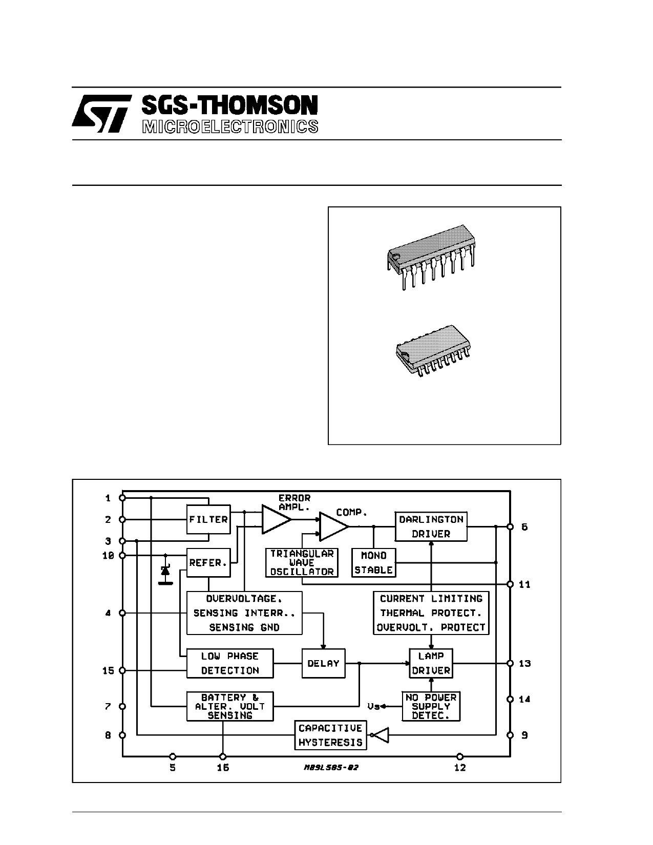
DIP16
DE SCRI PT I O N
The L585 is an integrated circuit designed for use
with an NPN darlington as a voltage regulator in a
threephase alternator charging system. It includes
fault diagnostic circuitry which drives a 3 W warning
lamp in fault conditions such as open or short circuit
connections. Protection against load dump tran-
sients, short circuits and low energy spikes is incor-
porated.
BLOCK DIAGRAM
SO16
ORDERING NUMBERS : L585 (DIP16)
L585D1 (SO16)
November 1991
1/9
1 page 
L585
ELECTRICAL CHARACTERISTICS (continued)
Symbol
Parameter
Test Conditions
Min. Typ. Max. Unit
PROTECTION
Tsh Darlingtyon Thermal Shutdown
Threshold
150 °C
VZen
V1dp
I1 3 sc
Idump
VZ13
(pin 10) Zener Voltage
IO = 60mA
IO = 130mA
Overvoltage Protection
Threshold (7)
Tj = 25°C
– 30°C < Tj < + 100°C
Lamp Driver Circuit Current
Pin 13 Dump Sustaining Capapility V1 3 = 110V@ Tj = 25°C
Current
V1 = 50V@ t = 100ms
Zener Clamping Voltage
I1 3 = 100mA@
t = < 3ms
6 8V
6.2 8.2 V
25 32 38
23 40
V
V
300 1500 mA
200 mA
110 V
I1 3 = 40mA@
t = < 6ms, full T
TJ = -30°C
100
90
V
V
Notes : 1. d = 50 % the duty cycle of the output signal at pin 6.
2. The lamp is switched on with a fixed delay when the alternator voltage becomes higher than VAH. (overcharge indication).
3. Measured 100 ms after turn-on.
4. The lamp is switched on with a fixed delay when the voltage Vp becomes lower than VPL (the alternator is not charging the battery).
5. The lamp is switched on when the cable B is broken (VA - VS becomes higher than VAS).
6. The lamp is switched on when the cable A is broken (IC without power voltage supply).
7. When the voltage at pin 1 is greater than V1 dp the internal darlington of the lamp is switched off.
CIRCUIT OPERATION
The L585 alternator regulator performs two main functions : regulation control and fault diagnostics.
REGULATION
The alternator voltage is compared with a reference
voltagein an error amplifier (see block diagram), the
output of which determines the duty cycle of the ex-
ternal darlington. This darlington switches the cur-
rent in the excitation coil of the alternator.
The switching frequencyis fixed and is set by the ex-
ternal capacitor COSC (see application circuit). Ca-
pacitive positive feedback and a monostable elimi-
natesspurious switching caused by contact bounce.
The basecurrent deliveredto the external darlington
it set by the resistor RB (see application circuit) and
must be dimensioned according to the charac-
teristics of this darlington and the maximum coil cur-
rent.
DI AG NO ST I C
This circuit receives informationfrom the battery,the
alternator and one alternator phase. It indicates
anomolousconditions by driving a 3 W lamp. To pre-
vent spurious fault warnings some indications are
not displayed immediately but are delayed by a fixed
time. No external components are needed to imple-
ment this delay since it is produced internally by di-
viding the internal oscillator with an eight-stage di-
vider to give a delay of 128 periods. For a one sec-
ond delay the oscillator frequency must be 128 Hz.
The lamp is driven after a delay when the following
conditions occur : no charge, break or short circuit
in the alternator sense wire.
The diagnostic lamp is driven immediately when the
cable connectingthe alternator to the battery is bro-
ken (Va-Vbatt above 2.6 typ.) or when the IC is with-
out power supply (VCE sat of the lamp driver is 2.4 V
typ. in this case).
5/9
5 Page | ||
| Páginas | Total 9 Páginas | |
| PDF Descargar | [ Datasheet L585D1.PDF ] | |
Hoja de datos destacado
| Número de pieza | Descripción | Fabricantes |
| L585D1 | CAR ALTERNATOR REGULATOR | STMicroelectronics |
| Número de pieza | Descripción | Fabricantes |
| SLA6805M | High Voltage 3 phase Motor Driver IC. |
Sanken |
| SDC1742 | 12- and 14-Bit Hybrid Synchro / Resolver-to-Digital Converters. |
Analog Devices |
|
DataSheet.es es una pagina web que funciona como un repositorio de manuales o hoja de datos de muchos de los productos más populares, |
| DataSheet.es | 2020 | Privacy Policy | Contacto | Buscar |