|
|
|
PDF L484 Data sheet ( Hoja de datos )
| Número de pieza | L484 | |
| Descripción | MAGNETIC PICKUP IGNITION CONTROLLER | |
| Fabricantes | STMicroelectronics | |
| Logotipo | ||
Hay una vista previa y un enlace de descarga de L484 (archivo pdf) en la parte inferior de esta página. Total 11 Páginas | ||
|
No Preview Available !
L484
MAGNETIC PICKUP IGNITION CONTROLLER
. DIRECT DRIVING OF THE EXTERNAL DAR-
LINGTON
. OPERATES WITH A WIDE RANGE OF MA-
GNETIC PICKUP TYPES
. CHARGING ANGLE (DWELL) CONTROL
. COIL CURRENT PEAK LIMITATION
. CONTINUOUS COIL CURRENT PROTECTION
. TACHOMETER SIGNAL OUTPUT
. EXTERNAL DARLINGTON OVERVOLTAGE
PROTECTION
. LOAD DUMP AND REVERSE BATTERY PRO-
TECTION
. POSSIBILITY OF SPARK POINT DELAYING
(ANTI KNOCK SYSTEM)
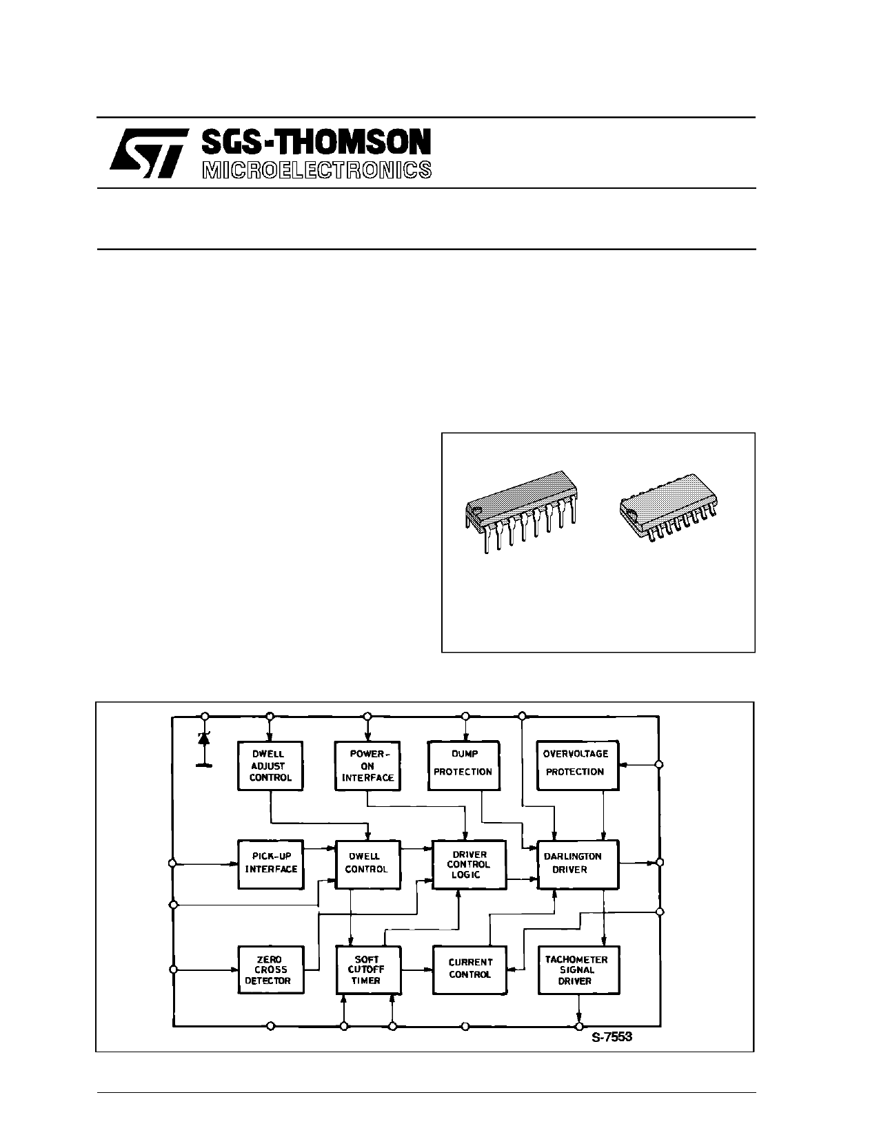
special design which has two input pins from the pic-
kup ; the first is the zero crossing detector for the
ignition command and the second pin is used to cal-
culate the dwell time. Moreover another pin is used
to adapt the L484 to various pickup types.
Other features of the device include darlington over-
voltage protection, dump protection, a supply volt-
age range of 6-28 V.
DESCRIPTION
The L484 is an integrated circuit designed for use
with an NPN darlington in breakerless ignition sy-
stems with magnetic pickup sensors and high ener-
gy ignition coils.
A key feature of the L484 is flexibility. It can be used
with a wide variety of magneticsensors thanks to the
BLOCK DIAGRAM
DIP16
SO16
ORDERING NUMBERS : L484 (DIP16)
L484D1 (SO16)
November 1991
1/11
1 page 
L484
DUMP PROTECTION
Symbol
Paramater
VDZ Zener Dump (pin 12)
Test Conditions
Ipin12 = 2mA
(*) Note 1 : TD/T is given by the formula :
TD
=
1
T 1 + I7D/I7C
(**) Note 2 :
TD
T
K
=
1 + I7D/I7C
K value depends on the pick–up used in the application ; typically K = 0.1
(***) Note 3 : the permanent conduction protection is guaranteed over the full temperature range
Min.
7.5
Typ.
Max.
9.5
Unit
V
CIRCUIT OPERATION
The L484 controls the charging angle (dwell) and
the peak value of the primary current in the coil over
the full range of operating conditions.
The coil current is limited to a predetermined level
by means of a negative feedback circuit including a
current sensing resistor, a comparator, the driver
stage and the power switch.
The dwell control circuit keeps the output stage in its
active region during current limitation. The time the
output stage is operating in the active region (desa-
turation time), is sufficient to compensate for possi-
ble variation in the energy stored due to the
acceleration of the motor ; moreover this time is li-
mited to avoid excessive power dissipation.
MAGNETIC PICK–UP CHARACTERISTICS
The typical magnetic pickup waveforms are shown
in fig. 1, the amplitude of the signal being a function
of the frequency. However on the market there are
many types of magnetic pickup, of which the wave-
forms may differ very much. Adjusting the value of
the resistor R11 on pin 2 and/or adding a resistor Ra
between the pin 6 (dwell adjust) and pin 11, as
shownin the applicationcircuit, it is possible to adapt
the L484 to a wide range of magnetic pickup wave-
forms.
Particularly by means of the resistor R11 on pin 2 it
is possible to define the maximum advance of the
conduction start into the coil . This is very useful at
high pick–up frequency.
CONTROL OF THE DWELL ANGLE
The dwell angle control circuit defines the conduc-
tion time of the output darlington, versus the speed
of rotation, the supply voltage and the charac-
teristics of the coil.
In each cycle the time the transistor operates in the
active region is compared with a reference time and
the error signal amplified to advance or delay the
conduction in the next cycle. To limit the power dis-
sipation the desaturation time is typically fixed
to 10% of the period T.
At very low frequencies the ON thershold is fixed at
200mV of the input signal and the desaturation time
is mainly determined by the peak waveform. This
positive thresholdalso prevents permanentconduc-
tion when the motor is stopped. When the input fre-
quency increases the dwell control gradually sets
the desaturationtime to 10% of the period. At higher
frequencies the ON threshold becomes negative to
permit a conduction angle of more than 50% always
keeping desaturation time to 10% of the period.
CURRENT LIMITING
The current in the coil is measured by means of a
voltage drop across a suitable resistor in the emitter
lead of the power transistor. When the threshold
voltage (260mV typ) is reached, the coil current is
kept constant via a feedback loop.
5/11
5 Page 
L484
Information furnished is believed to be accurate and reliable. However, SGS-THOMSON Microelectronics assumes no responsibility for
the consequences of use of such information nor for any infringement of patents or other rights of third parties which may result from its
use. No license is granted by implication or otherwise under any patent or patent rights of SGS-THOMSON Microelectronics. Specifica-
tions mentioned in this publication are subject to change without notice. This publication supersedes and replaces all information pre-
viously supplied. SGS-THOMSON Microelectronics products are not authorized for use as critical components in life support devices or
systems without express written approval of SGS-THOMSON Microelectronics.
© 1994 SGS-THOMSON Microelectronics - All Rights Reserved
SGS-THOMSON Microelectronics GROUP OF COMPANIES
Australia - Brazil - France - Germany - Hong Kong - Italy - Japan - Korea - Malaysia - Malta - Morocco - The Netherlands - Singapore -
Spain - Sweden - Switzerland - Taiwan - Thaliand - United Kingdom - U.S.A.
11/11
11 Page | ||
| Páginas | Total 11 Páginas | |
| PDF Descargar | [ Datasheet L484.PDF ] | |
Hoja de datos destacado
| Número de pieza | Descripción | Fabricantes |
| L4805 | VERY LOWDROP VOLTAGE REGULATORS | STMicroelectronics |
| L4808 | VERY LOWDROP VOLTAGE REGULATORS | STMicroelectronics |
| L4808-L4810-L4812 | VERY LOWDROP VOLTAGE REGULATORS | STMicroelectronics |
| L4808CV | VERY LOWDROP VOLTAGE REGULATORS | STMicroelectronics |
| Número de pieza | Descripción | Fabricantes |
| SLA6805M | High Voltage 3 phase Motor Driver IC. |
Sanken |
| SDC1742 | 12- and 14-Bit Hybrid Synchro / Resolver-to-Digital Converters. |
Analog Devices |
|
DataSheet.es es una pagina web que funciona como un repositorio de manuales o hoja de datos de muchos de los productos más populares, |
| DataSheet.es | 2020 | Privacy Policy | Contacto | Buscar |