|
|
|
PDF KSZ8051RNL Data sheet ( Hoja de datos )
| Número de pieza | KSZ8051RNL | |
| Descripción | 10Base-T/100Base-TX Physical Layer Transceiver | |
| Fabricantes | Micrel Semiconductor | |
| Logotipo | ||
Hay una vista previa y un enlace de descarga de KSZ8051RNL (archivo pdf) en la parte inferior de esta página. Total 30 Páginas | ||
|
No Preview Available !
KSZ8051MNL/RNL
10Base-T/100Base-TX
Physical Layer Transceiver
General Description
Features
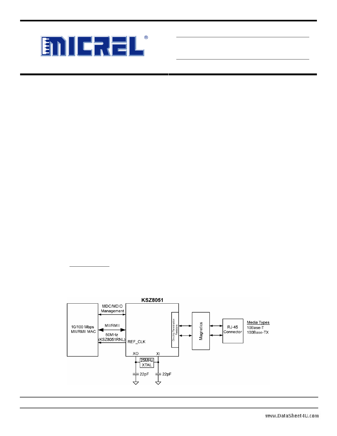
The KSZ8051 is a single supply 10Base-T/100Base-TX
Ethernet physical layer transceiver for transmission and
reception of data over standard CAT-5 unshielded twisted
pair (UTP) cable.
The KSZ8051 is a highly integrated, compact solution. It
reduces board cost and simplifies board layout by using
on-chip termination resistors for the differential pairs and
by integrating a low noise regulator to supply the 1.2V
core.
The KSZ8051MNL offers the Media Independent Interface
(MII) and the KSZ8051RNL offers the Reduced Media
Independent Interface (RMII) for direct connection with MII/
RMII compliant Ethernet MAC processors and switches.
A 25MHz crystal is used to generate all required clocks,
including the 50MHz RMII reference clock output for the
KSZ8051RNL.
The KSZ8051 provides diagnostic features to facilitate
system bring-up and debugging in production testing and
in product deployment. Parametric NAND tree support
enables fault detection between KSZ8051 I/Os and board.
Micrel LinkMD® TDR-based cable diagnostics permit
identification of faulty copper cabling.
The KSZ8051MNL and KSZ8051RNL are available in 32-
pin, lead-free QFN packages (See Ordering Information).
Data sheets and support documentation can be found on
Micrel’s web site at: www.micrel.com.
• Single-chip 10Base-T/100Base-TX IEEE 802.3
compliant Ethernet Transceiver
• MII Interface support (KSZ8051MNL)
• RMII v1.2 Interface support with 50MHz reference clock
output to MAC, and option to input 50MHz reference
clock (KSZ8051RNL)
• Back-to-Back mode support for 100Mbps copper
repeater or media converter
• MDC/MDIO Management Interface for PHY register
configuration
• Programmable interrupt output
• LED outputs for link, activity and speed status indication
• On-chip termination resistors for the differential pairs
• Baseline Wander Correction
• HP Auto MDI/MDI-X for reliable detection and
correction for straight-through and crossover cables
with disable and enable option
• Auto-negotiation to automatically select the highest link
up speed (10/100 Mbps) and duplex (half/full)
• Power down and power saving modes
• LinkMD® TDR-based cable diagnostics for identification
of faulty copper cabling
• Parametric NAND Tree support for fault detection
between chip I/Os and board.
____________________________________________________________________________________________________________
Functional Diagram
www.DataSheet4U.com
LinkMD is a registered trademark of Micrel, Inc.
Micrel Inc. • 2180 Fortune Drive • San Jose, CA 95131 • USA • tel +1 (408) 944-0800 • fax + 1 (408) 474-1000 • http://www.micrel.com
July 2010
M9999-070910-1.0
1 page 
Micrel, Inc.
KSZ8051MNL/RNL
Transmit Enable (TXEN) .............................................................................................................................................. 25
Transmit Data [1:0] (TXD[1:0]) ..................................................................................................................................... 25
Carrier Sense/Receive Data Valid (CRS_DV).............................................................................................................. 25
Receive Data [1:0] (RXD[1:0]) ...................................................................................................................................... 25
Receive Error (RXER) .................................................................................................................................................. 25
Collision Detection........................................................................................................................................................ 25
RMII Signal Diagram......................................................................................................................................................... 25
RMII – 25MHz Clock Mode........................................................................................................................................... 26
RMII – 50MHz Clock Mode........................................................................................................................................... 26
Back-to-Back Mode – 100Mbps Copper Repeater / Media Converter............................................................................ 27
MII Back-to-Back Mode (KSZ8051MNL only)................................................................................................................... 27
RMII Back-to-Back Mode (KSZ8051RNL only) ................................................................................................................ 28
MII Management (MIIM) Interface....................................................................................................................................... 28
Interrupt (INTRP) ................................................................................................................................................................. 29
HP Auto MDI/MDI-X ............................................................................................................................................................. 29
Straight Cable ................................................................................................................................................................... 29
Crossover Cable ............................................................................................................................................................... 30
LinkMD® Cable Diagnostics................................................................................................................................................ 30
NAND Tree Support ............................................................................................................................................................ 30
NAND Tree I/O Testing..................................................................................................................................................... 32
Power Management ............................................................................................................................................................ 32
Power Saving Mode.......................................................................................................................................................... 32
Energy Detect Power Down Mode ................................................................................................................................... 32
Power Down Mode ........................................................................................................................................................... 32
Slow Oscillator Mode ........................................................................................................................................................ 32
Reference Circuit for Power and Ground Connections .................................................................................................. 33
Register Map........................................................................................................................................................................ 34
Register Description ........................................................................................................................................................... 34
Register Description (Continued)...................................................................................................................................... 35
Register Description (Continued)...................................................................................................................................... 36
Register Description (Continued)...................................................................................................................................... 37
Register Description (Continued)...................................................................................................................................... 38
Register Description (Continued)...................................................................................................................................... 39
Register Description (Continued)...................................................................................................................................... 40
Register Description (Continued)...................................................................................................................................... 41
Register Description (Continued)...................................................................................................................................... 42
Register Description (Continued)...................................................................................................................................... 43
wwAbws.DoalutatSehMeeat4xUim.coumm Ratings(1) ............................................................................................................................................ 44
Operating Ratings(2) ............................................................................................................................................................ 44
Electrical Characteristics(3) ................................................................................................................................................ 44
Electrical Characteristics(3) (Continued) ........................................................................................................................... 45
Timing Diagrams ................................................................................................................................................................. 46
MII SQE Timing (10Base-T) ............................................................................................................................................. 46
July 2010
5 M9999-070910-1.0
5 Page 
Micrel, Inc.
KSZ8051MNL/RNL
Pin Number Pin Name
NAND_Tree#
Type(1)
Pin Function
Config Mode:
The pull-up/pull-down value is latched as NAND Tree# at the
de-assertion of reset. See “Strapping Options” section for details.
22
TXC
I/O MII Mode:
MII Transmit Clock Output
MII Back-to-Back Mode: MII Transmit Clock Input
23 TXEN I MII Mode: MII Transmit Enable Input
24 TXD0 I MII Mode: MII Transmit Data Input[0](3)
25 TXD1 I MII Mode: MII Transmit Data Input[1](3)
26 TXD2 I MII Mode: MII Transmit Data Input[2](3)
27 TXD3 I MII Mode: MII Transmit Data Input[3](3)
28
COL /
Ipd/O
MII Mode:
MII Collision Detect Output /
CONFIG0
Config Mode: The pull-up/pull-down value is latched as CONFIG0 at the
de-assertion of reset. See “Strapping Options” section for details.
29
CRS /
Ipd/O
MII Mode:
MII Carrier Sense Output /
CONFIG1
Config Mode: The pull-up/pull-down value is latched as CONFIG1 at the
de-assertion of reset. See “Strapping Options” section for details.
30
LED0 /
Ipu/O
LED Output:
Programmable LED0 Output /
NWAYEN
Config Mode: Latched as Auto-Negotiation Enable (register 0h, bit 12) at the
de-assertion of reset. See “Strapping Options” section for details.
The LED0 pin is programmable via register 1Fh bits [5:4], and is defined as follows.
LED mode = [00]
Link/Activity
No Link
Pin State
High
Link Low
Activity
Toggle
LED Definition
OFF
ON
Blinking
LED mode = [01]
Link
Pin State
No Link
High
Link Low
LED Definition
OFF
ON
31 LED1 /
SPEED
www.DataSheet4U.com
Ipu/O
LED mode = [10], [11]
Reserved
LED Output:
Programmable LED1 Output /
Config Mode: Latched as SPEED (register 0h, bit 13) at the de-assertion of
reset.
See “Strapping Options” section for details.
The LED1 pin is programmable via register 1Fh bits [5:4], and is defined as follows.
LED mode = [00]
Speed
10Base-T
100Base-TX
Pin State
High
Low
LED Definition
OFF
ON
LED mode = [01]
Activity
Pin State
No Activity
High
LED Definition
OFF
July 2010
11 M9999-070910-1.0
11 Page | ||
| Páginas | Total 30 Páginas | |
| PDF Descargar | [ Datasheet KSZ8051RNL.PDF ] | |
Hoja de datos destacado
| Número de pieza | Descripción | Fabricantes |
| KSZ8051RNL | 10BASE-T/100BASE-TX Automotive Physical Layer Transceiver | Microchip |
| KSZ8051RNL | 10Base-T/100Base-TX Physical Layer Transceiver | Micrel Semiconductor |
| KSZ8051RNLU | 10Base-T/100Base-TX Physical Layer Transceiver | Micrel Semiconductor |
| Número de pieza | Descripción | Fabricantes |
| SLA6805M | High Voltage 3 phase Motor Driver IC. |
Sanken |
| SDC1742 | 12- and 14-Bit Hybrid Synchro / Resolver-to-Digital Converters. |
Analog Devices |
|
DataSheet.es es una pagina web que funciona como un repositorio de manuales o hoja de datos de muchos de los productos más populares, |
| DataSheet.es | 2020 | Privacy Policy | Contacto | Buscar |