|
|
|
PDF LM27952 Data sheet ( Hoja de datos )
| Número de pieza | LM27952 | |
| Descripción | White LED Adaptive 1.5X/1X Switched Capacitor Current Driver | |
| Fabricantes | National Semiconductor | |
| Logotipo | ||
Hay una vista previa y un enlace de descarga de LM27952 (archivo pdf) en la parte inferior de esta página. Total 8 Páginas | ||
|
No Preview Available !
May 2005
www.DataSheet4U.com
LM27952
White LED Adaptive 1.5X/1X Switched Capacitor Current
Driver
General Description
The LM27952 is a switched capacitor white-LED driver ca-
pable of driving up to 4 LEDs with 30mA through each LED.
Its 4 tightly regulated current sinks ensure excellent LED
current and brightness matching. LED drive current is pro-
grammed by an external sense resistor. The LM27952 oper-
ates over an input voltage range from 3.0V to 5.5V and
requires only four low-cost ceramic capacitors.
The LM27952 provides excellent efficiency without the use
of an inductor by operating the charge pump in a gain of 3/2,
or in a gain of 1. Maximum efficiency is achieved over the
input voltage range by actively selecting the proper gain
based on the LED forward voltage requirements.
The LM27952 uses constant frequency pre-regulation to
minimize conducted noise on the input. It has a fixed 750kHz
switching frequency optimized for portable applications. The
LM27952 consumes less than 1µA of supply current when
shut down.
The LM27952 is available in a 14-pin No-Pullback Leadless
Leadframe Package: LLP-14.
Features
n Drives up to 4 LEDs with up to 30mA each
n Regulated current sources with 0.2%(typ.) matching
n 3/2x, 1x Gain transition based on LED VF
n Peak Efficiency Over 85%
n Input Voltage Range: 3.0V to 5.5V
n PWM Brightness Control
n Very Small Solution Size - NO INDUCTOR
n Fixed 750kHz Switching Frequency
n <1µA Shutdown Current
n 14-pin LLP Package: 4.0mm X 3.0mm X 0.8mm
Applications
n White LED Display Backlights
n White LED Keypad Backlights
n General Purpose LED Lighting
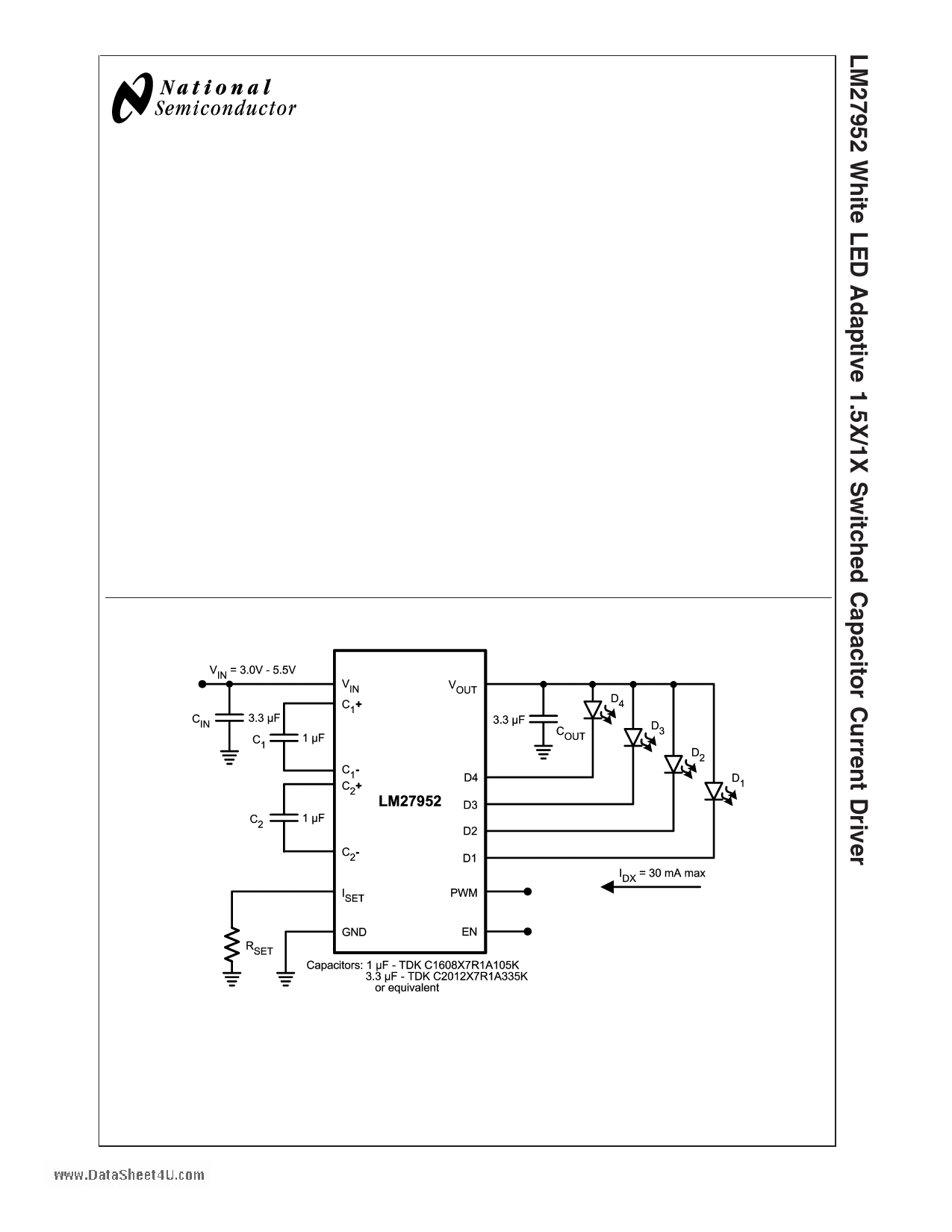
Typical Application Circuit
© 2005 National Semiconductor Corporation DS201480
20148001
www.national.com
1 page 
Application Information
CIRCUIT DESCRIPTION
The LM27952 is an adaptive 1.5x/1x CMOS charge pump,
optimized for driving white LEDs used in backlighting small-
format displays. It provides four constant current inputs ca-
pable of sinking up to 30mA through each LED. The well-
matched current sinks ensure the current through all the
LEDs are virtually identical, providing a uniform brightness
across the entire display.
Each LED is driven from VOUT and connected to one of the
four current sinks. LED drive current is programmed by
connecting a resistor, RSET, to the current set pin, ISET. LED
brightness is adjusted by applying a Pulse Width Modulated
(PWM) signal to the dedicated PWM input pin.
CHARGE PUMP
The input to the 1.5x/1x charge pump is connected to the VIN
pin, and the loosely regulated output of the charge pump is
connected to the VOUT pin. The recommended input voltage
range of the LM27952 is 3.0V to 5.5V. The device’s loosely-
regulated charge pump has both open loop and closed loop
modes of operation. When the device is in open loop, the
voltage at VOUT is equal to the gain times the voltage at the
input. When the device is in closed loop, the voltage at VOUT
is loosely regulated to 4.5V (typ.). The charge pump gain
transitions are actively selected to maintain regulation based
on LED forward voltage and load requirements. This allows
the charge pump to stay in the most efficient gain (1x) over
as much of the input voltage range as possible, reducing the
power consumed from the battery.
SOFT START
The LM27952 contains internal soft-start circuitry to limit
input inrush currents when the part is enabled. Soft start is
implemented internally with a controlled turn-on of the inter-
nal voltage reference. Due to the soft-start circuitry, startup
time of the LM27952 is approximately 330µs (typ.).
ENABLE AND PWM PINS
The LM27952 has 2 logic control pins. Both pins are active-
high logic (HIGH = ON). There is an internal pull-down
resistor (150kΩ typ.) connected between the enable pin (EN)
and GND. There is no pull-up or pull-down connected to the
Pulse Width Modulated (PWM) pin.
The EN pin is the master enable pin for the part. When the
voltage on this pin is low (<0.4V), the part is in shutdown
mode. In this mode, all internal circuitry is OFF and the part
consumes very little supply current (<1µA typ.). When the
voltage on the EN pin is high (>1.0V), the part will activate
the charge pump and regulate the output voltage to its
nominal value.
The PWM pin serves as a dedicated logic input for LED
brightness control. When the voltage on this pin is low
(<0.4V), the current sinks will be turned off and no current
will flow through the LEDs. When the voltage on this pin is
high (>1.0V), the currents sinks will turn on and regulate to
the current level set by the resistor connected to the ISET pin.
SETTING LED CURRENTS
The current through the four LEDs connected to D1-4 can be
set to a desired level simply by connecting an appropriately
sized resistor (RSET) between the ISET pin of the LM27952
and GND. The LED currents are proportional to the current
that flows out of the ISET pin and are a factor of 200 times
greater than the ISET current. The feedback loop of an inter-
nal amplifier sets the voltage of the ISET pinwtwow1..D25aVta(Styhpe.e).t4U.com
The statements above are simplified in the equations below:
IDx = 200 x(VSET / RSET)
RSET = 200 x (1.25V / IDx)
ADJUSTING LED BRIGHTNESS (PWM control)
Perceived LED brightness can be adjusted using a PWM
control signal on the LM27952 PWM logic input pin, turning
the current sources ON and OFF at a rate faster than per-
ceptible by the eye. When this is done, the total brightness
perceived is proportional to the duty cycle (D) of the PWM
signal (D = the percentage of time that the LED is on in every
PWM cycle). A simple example: if the LEDs are driven at
15mA each with a PWM signal that has a 50% duty cycle,
perceived LED brightness will be about half as bright as
compared to when the LEDs are driven continuously with
15mA.
The minimum recommended PWM frequency is 100Hz. Fre-
quencies below this may be visibly noticeable as flicker or
blinking. The maximum recommended PWM frequency is
1kHz. Frequencies above this may cause interference with
internal current driver circuitry and/or noise in the audible
range. Due to the regulation control loop, the maximum
frequency and minimum duty cycle applied to the PWM pin
should be chosen such that the minimum ON time is no less
than 30µs in duration. If a PWM signal is applied to the EN
pin instead, the maximum frequency and minimum duty
cycle should be chosen to accommodate both the LM27952
startup time (330µs typ.) and the 30µs control loop delay.
The preferred method to adjust brightness is to keep the
master EN voltage ON continuously and apply a PWM signal
to the dedicated PWM input pin. The benefit of this type of
connection can be best understood with a contrary example.
When a PWM signal is connected to the master enable (EN)
pin, the charge pump repeatedly turns on and off. Every time
the charge pump turns on, there is an inrush of current as the
capacitances, both internal and external, are recharged. This
inrush current results in a current spike and a voltage dip at
the input of the part. By only applying the PWM signal to
PWM logic input pin, the charge pump continuously stays
on, resulting in much lower input noise.
In cases where a PWM signal must be connected to the EN
pin, measures can be taken to reduce the magnitude of the
charge-pump turn-on transient response. More input capaci-
tance, series resistors and/or ferrite beads may provide ben-
efits. If the current spikes and voltage dips can be tolerated,
connecting the PWM signal to the EN pin does provide a
benefit of lower supply current consumption. When the PWM
signal to the EN pin is low, the LM27952 will be shutdown
and input current will only be a few micro-amps. This results
in a lower time-averaged input current than the prior sugges-
tion, where EN is kept on continuously.
MAXIMUM OUTPUT CURRENT, MAXIMUM LED
VOLTAGE, MINIMUM INPUT VOLTAGE
The LM27952 can drive 4 LEDs at 30mA each from an input
voltage as low as 3.0V, so long as the LEDs have a forward
voltage of 3.5V or less (room temperature).
The statement above is a simple example of the LED drive
capabilities of the LM27952. The statement contains key
application parameters required to validate an LED-drive
design using the LM27952: LED current (ILED), number of
active LEDs (N), LED forward voltage (VLED), and minimum
input voltage (VIN-MIN).
5 www.national.com
5 Page | ||
| Páginas | Total 8 Páginas | |
| PDF Descargar | [ Datasheet LM27952.PDF ] | |
Hoja de datos destacado
| Número de pieza | Descripción | Fabricantes |
| LM2795 | LM2794/LM2795 Current Reg Switched Cap LED Sup w/Analog PWM Brightness Control (Rev. L) | Texas Instruments |
| LM27951 | Switched-Capacitor Current Driver (Rev. C) | Texas Instruments |
| LM27951 | White LED Adaptive 1.5X/1X Switched Capacitor Current Driver | National Semiconductor |
| LM27952 | LM27952 White LED Adaptive 1.5X/1X Switched Capacitor Current Driver (Rev. B) | Texas Instruments |
| Número de pieza | Descripción | Fabricantes |
| SLA6805M | High Voltage 3 phase Motor Driver IC. |
Sanken |
| SDC1742 | 12- and 14-Bit Hybrid Synchro / Resolver-to-Digital Converters. |
Analog Devices |
|
DataSheet.es es una pagina web que funciona como un repositorio de manuales o hoja de datos de muchos de los productos más populares, |
| DataSheet.es | 2020 | Privacy Policy | Contacto | Buscar |