|
|
|
PDF SC2446 Data sheet ( Hoja de datos )
| Número de pieza | SC2446 | |
| Descripción | Dual-Phase Single or Two Output Synchronous Step-Down Controller | |
| Fabricantes | Semtech Corporation | |
| Logotipo | ||
Hay una vista previa y un enlace de descarga de SC2446 (archivo pdf) en la parte inferior de esta página. Total 30 Páginas | ||
|
No Preview Available !
SC2446
Dual-Phase Single or Two Output
Synchronous Step-Dowwwwn.DaCtaoShenett4rUo.collmers
POWER MANAGEMENT
Description
The SC2446 is a high-frequency dual synchronous step-
down switching power supply controller. It provides out-
of-phase high-current output gate drives to all N-chan-
nel MOSFET power stages. The SC2446 operates in syn-
chronous continuous-conduction mode. Both phases are
capable of maintaining regulation with sourcing or sink-
ing load currents, making the SC2446 suitable for gen-
erating both VDDQ and the tracking VTT for DDR applica-
tions.
The SC2446 employs fixed frequency peak current-mode
control for the ease of frequency compensation and fast
transient response.
The dual-phase step-down controllers of the SC2446 can
be configured to provide two individually controlled and
regulated outputs or a single output with shared current
in each phase. The Step-down controllers operate from an
input of at least 4.7V and are capable of regulating out-
puts as low as 0.5V
The step-down controllers in the SC2446 have the pro-
vision to sense a synthesized MOSFET RDS(ON) for cur-
rent-mode control. This sensing scheme (U.S. patent
6,441,597) eliminates the need of the current-sense re-
sistor and is more noise-immune than direct sensing of
the high-side or the low-side MOSFET voltage. Precise cur-
rent-sensing with sense resistor is optional.
Individual soft-start and overload shutdown timer is in-
cluded in each step-down controller. The SC2446 imple-
ments hiccup overload protection. In two-phase single-
output configuration, the master timer controls the soft-
start and overload shutdown functions of both control-
lers.
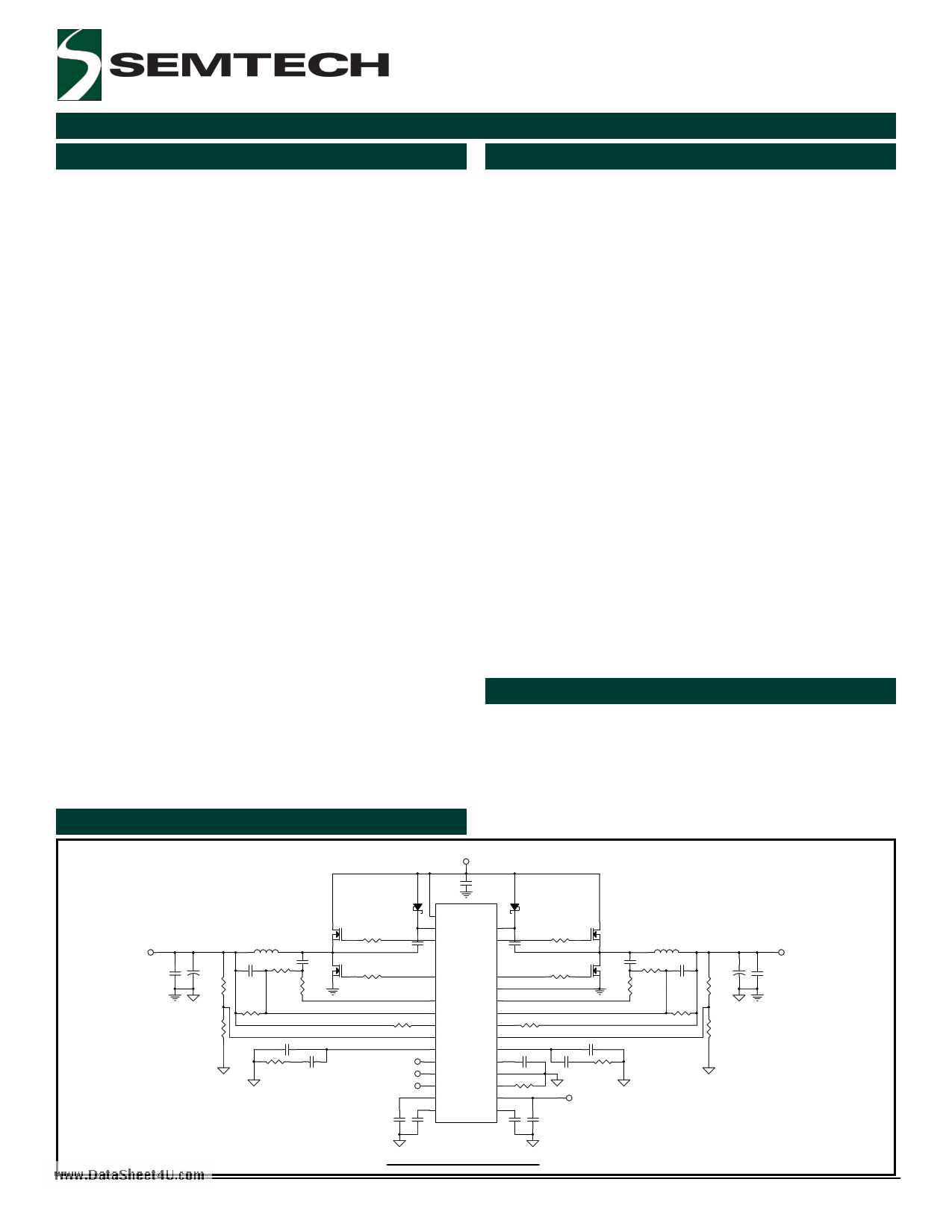
Typical Application Circuit
Features
2-Phase synchronous continuous conduction mode
for high efficiency step-down converters
Out of phase operation for low input current ripples
Output source and sink currents
Fixed frequency peak current-mode control
75mV/-110mV maximum current sense voltage
Synthesized MOSFET RDS(ON) current-sensing for
low-cost applications
Optional resistor current-sensing for precise current-
limit
Dual outputs or 2-phase single output operation
Excellent current sharing between individual phases
Wide input voltage range: 4.7V to 16V
Individual soft-start, overload shutdown and enable
Duty cycle up to 88%
0.5V feedback voltage for low-voltage outputs
External reference input for DDR applications
Buffered VDDQ/2 output
Programmable frequency up to 1 MHz per phase
External synchronization
Industrial temperature range
28-lead TSSOP - EDP package
Applications
Telecommunication power supplies
DDR memory power supplies
Graphic power supplies
Servers and base stations
VIN
Figure 1
VO2
C99 C95
+
R79
R81
L11
C96 R75
RCS+
Q21
Q23
CFILTER
RFILTER
C101
R83 C103
C92
D11 D12
R73
C93
PVCC
BST2
GDH2
BST1
GDH1
C94
Q22
R74
L12
R77
RCS-
REF
VIN
SYNC
C106
GDL2
GDL1
Q24
R78
PGND
VPN2
VPN1
CS2+
CS2-
CS1+
CS1-
RCS-
IN2-
COMP2
REFIN
IN1-
COMP1
REF
C104
C102
C105
VIN2
SYNC
SS1/EN1
AGND
Rosc
AVCC
R85
VIN
SS2/EN2 REFOUT
C107
C108
U1
SC2446
C109
CFILTER
RFILTER
R84
R76
C97
RCS+
Dual Independant Outputs
VO1
C98
+
R80
C100
R82
Revision: September 9, 2004
1 U.S. Patent No. 6,441,597, www.semtech.com
1 page 
SC2446
POWER MANAGEMENT
Electrical Characteristics (Cont.)
Unless specified: AVCC = PVCC = VIN2 =12V, VBST1 = VBST2 = 12V, SYNC= 0, ROSC = 51.1kΩ, -40°C < TA = TJ < 85°C
Parameter
Symbol
Conditions
Min
Load Regulation
Internal 0.5V Reference Buffer
0 < IREFOUT < -5mA
Output Voltage
VREF
IREF= -1mA
Load Regulation
0 < IREF < -5mA
Notes:
(1) Guaranteed by design not tested in production.
(2) This device is ESD sensitive. Use of standard ESD handling precautions is required.
490
www.DataSheet4U.com
Typ
0.02
Max
Units
%/mA
500 510 mV
0.05 %/mA
Pin Configurations
(TOP VIEW)
CS1+
CS1-
ROSC
IN1-
COMP1
SYNC
AGND
REF
REFOUT
REFIN
COMP2
IN2-
CS2-
CS2+
(28-Pin TSSOP)
Figure 2
SS1/EN1
VPN1
BST1
GDH1
GDL1
PVCC
PGND
GDL2
GDH2
BST2
VPN2
VIN2
AVCC
SS2/EN2
Ordering Information
Device
Package(1)
Temp. Range( TA)
SC2446ITETRT(2) TSSOP-28-EDP
-40 to 85°C
SC2446EVB
Evaluation Board
Notes:
(1) Only available in tape and reel packaging. A reel
contains 2500 devices for TSSOP package.
(2) Lead free product.
2004 Semtech Corp.
5
www.semtech.com
5 Page 
SC2446
POWER MANAGEMENT
Application Information
www.DataSheet4U.com
SC2446 consists of two current-mode synchronous buck
controllers with many integrated functions. By proper
application circuitry configuration, SC2446 can be used
to generate
1) two independent outputs from a common input or two
different inputs or
2) dual phase output with current sharing,
3) current sourcing/sinking from common or separate
inputs as in DDR (I and II) memory application.
The application information related to the converter design
using SC2446 is described in the following.
Step-down Converter
Starting from the following step-down converter
specifications,
Input voltage range: Vin ∈ [Vin,min, Vin,max ]
Input voltage ripple
Output voltage: Vo
(peak-to-peak):
∆Vin
Output voltage accuracy: ε
Output voltage ripple (peak-to-peak): ∆Vo
Nominal output (load) current:
Maximum output current limit:
IIoo,max
Output (load) current transient slew rate: dIo (A/s)
Circuit efficiency: η
Selection criteria and design procedures for the following
are described.
1) output inductor (L) type and value,
2) output capacitor (Co) type and value,
3)
4)
pinopwuetrcMapOaScFiEtoTr’s(,Cin)
type
and
value,
5) current sensing and limiting circuit,
6) voltage sensing circuit,
7) loop compensation network.
Operating Frequency (fs)
The switching frequency in the SC2446 is user-
programmable. The advantages of using constant
frequency operation are simple passive component
selection and ease of feedback compensation. Before
setting the operating frequency, the following trade-offs
should be considered.
1) Passive component size
2) Circuitry efficiency
3) EMI condition
4) Minimum switch on time and
5) Maximum duty ratio
For a given output power, the sizes of the passive
components are inversely proportional to the switching
frequency, whereas MOSFET’s/Diodes switching losses are
proportional to the operating frequency. Other issues such
as heat dissipation, packaging and the cost issues are
also to be considered. The frequency bands for signal
transmission should be avoided because of EM
interference.
Minimum Switch On Time Consideration
In the SC2446 the falling edge of the clock turns on the
top MOSFET. The inductor current and the sensed voltage
ramp up. After the sensed voltage crosses a threshold
determined by the error amplifier output, the top MOSFET
is turned off. The propagation delay time from the turn-
on of the controlling FET to its turn-off is the minimum
switch on time. The SC2446 has a minimum on time of
about 150ns at room temperature. This is the shortest
on interval of the controlling FET. The controller either does
not turn on the top MOSFET at all or turns it on for at least
150ns.
For a synchronous step-down converter, the operating duty
cycle is VO/VIN. So the required on time for the top MOSFET
is VO/(VINfs). If the frequency is set such that the required
pulse width is less than 150ns, then the converter will
start skipping cycles. Due to minimum on time limitation,
simultaneously operating at very high switching frequency
and very short duty cycle is not practical. If the voltage
conversion ratio VO/VIN and hence the required duty cycle
is higher, the switching frequency can be increased to reduce
the sizes of passive components.
There will not be enough modulation headroom if the on
time is simply made equal to the minimum on time of the
SC2446. For ease of control, we recommend the required
pulse width to be at least 1.5 times the minimum on time.
2004 Semtech Corp.
11
www.semtech.com
11 Page | ||
| Páginas | Total 30 Páginas | |
| PDF Descargar | [ Datasheet SC2446.PDF ] | |
Hoja de datos destacado
| Número de pieza | Descripción | Fabricantes |
| SC2440 | 2.5 MHz Dual Switching Regulator | Semtech Corporation |
| SC2441 | Very Low Input Voltage 2-Phase Synchronous Step-down Controllers with Step-up Converter | Semtech Corporation |
| SC2441A | 1.8V to 20V Input 2-Phase Synchronous Step-down Controllers with Step-up Converter | Semtech Corporation |
| SC2442 | High Performance Wide Input Range Dual Synchronous Buck Controller | Semtech Corporation |
| Número de pieza | Descripción | Fabricantes |
| SLA6805M | High Voltage 3 phase Motor Driver IC. |
Sanken |
| SDC1742 | 12- and 14-Bit Hybrid Synchro / Resolver-to-Digital Converters. |
Analog Devices |
|
DataSheet.es es una pagina web que funciona como un repositorio de manuales o hoja de datos de muchos de los productos más populares, |
| DataSheet.es | 2020 | Privacy Policy | Contacto | Buscar |