|
|
|
PDF SC2441 Data sheet ( Hoja de datos )
| Número de pieza | SC2441 | |
| Descripción | Very Low Input Voltage 2-Phase Synchronous Step-down Controllers with Step-up Converter | |
| Fabricantes | Semtech Corporation | |
| Logotipo | ||
Hay una vista previa y un enlace de descarga de SC2441 (archivo pdf) en la parte inferior de esta página. Total 30 Páginas | ||
|
No Preview Available !
SC2441
Very Low Input Voltage 2-Phase Synchronous
Step-down Controllers with Swtwewp.D-autapShCeeot4nU.vcoemrter
POWER MANAGEMENT
Description
Features
The SC2441 is a high-frequency triple output switching
regulator controller. It consists of a dual out-of-phase
synchronous step-down PWM controller with high-current
output gate drives and a 1.7A integrated step-up switch-
ing regulator.
The dual-phase step-down controller of the SC2441 can
be configured to provide two individually controlled and
regulated outputs or a single output with shared current
in each phase. The buck controller can operate from an
input voltage of at least 4.72V or they can run off a supply
generated locally with the integrated boost regulator. This
makes the SC2441 ideally suited for applications where a
low-voltage input (3.3V, 2.5V, or 1.8V) is to be stepped
down for lower voltage logic yet the input is too low to
drive power MOSFET’s efficiently. The boost regulator can
be used to provide a third auxiliary output while generat-
ing the bias for the buck controllers.
Both the step-down controllers and the step-up regulator
employ fixed frequency peak current-mode control for fast
transient response. The master oscillator frequency can
be programmed by the user.
Individual soft-start and overload shutdown timer are em-
ployed in each step-down controller for hiccup overload
protection. In single-output configuration, the channel 1
timer controls the soft-start and overload shutdown func-
tions of both controllers.
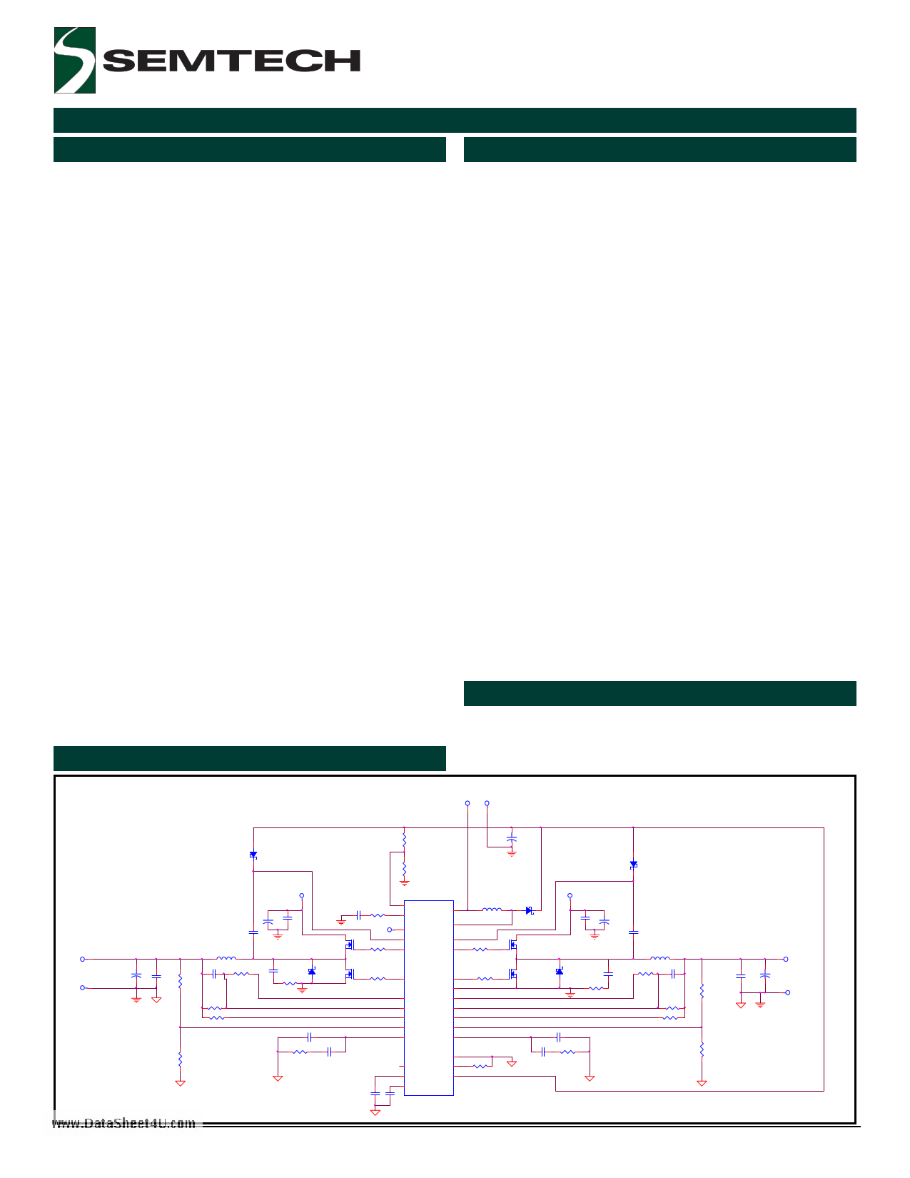
Typical Application Circuit
2-Phase Synchronous step-down controllers
2-Phase Synchronous Continuous Conduction Mode
For High Efficiency Step-down Converters
Out of Phase Operation For Low Input Current Ripples
Operates Up To 1MHz Per Channel
Configurable Dual Outputs Or 2-Phase Single Output
Operation with Peak Current Mode Control
Excellent Current Sharing Between Phases
Wide Input Voltage Range: 1.8V to 15V
Duty Cycle Up to 90%
0.5V Feedback Voltages For Low-Voltage Outputs
Precision 50mV Current-Limit Threshold
Patented Combi-sense Technique for High SNR of Cur-
rent-Sensing
Individual Soft-Start, Overload Shutdown and Enable
Step-up Regulator
Wide Input Voltage Range: 1.8V to 15V
Operates At Twice The Individual Channel Frequency
Of The Buck Controllers
0.23V VCESAT Switch at 1A
Fixed Frequency with Current-Mode Control
Common Features
External Synchronization
Industrial Temperature Range
Applications
Low Voltage Distributed DC-DC Converters
Telecommunication Power Supplies
Servers and base stations
VIN VINGND
R12 + C38
D1
R14
D2
VO1
VO1GND
C18
C8
+
C25
R9
L1
C20
R5
RCS+1
RCS-1
R17
Figure 1
Revision: January 10, 2005
VIN
+ C1
C2
C19
R10
Q1
D7
Q6
C27
R18 C30
C36
R28
7 FB3
8 COMP3
VIN
28 PVIN
R3
18 BST2
19 GDH2
IN 1
PH3 27
BST1
GDH1
25
23
SC2441
R7
20 GDL2
GDL1 22
PGND 24
2 VPN2
VPN1 26
16 CS2+
CS1+ 4
15 CS2-
CS1- 5
14 FB2
FB1 11
13 COMP2
COMP1 12
GND 9
6 SY NC
Rosc 10
3 SS1/EN1
VCC 21
17 SS2/EN2
C32
C33
U1
L3
R4
R8
R20
1
D3
Q2
Q7
VIN
C3 + C4
C17
D10 C23
R13
L2
R6 C21
RCS+2
C28
C31 R19
RCS-2
R11
R16
VO2
C24
C15
+
VO2GND
US patent 6,441,597 www.semtech.com
1 page 
POWER MANAGEMENT
Pin Configurations
IN
VPN2
SS1/EN1
CS1+
CS1-
SYNC/SHDN
FB3
COMP3
GND
ROSC
FB1
COMP1
COMP2
FB2
(TOP VIEW)
1 28
2 27
3 26
4 25
5 24
6 23
7 22
8 21
9 20
10 19
11 18
12 17
13 16
14 15
(28-Pin TSSOP)
SC2441
PVIN
PH3
VPN1
BST1
PGND
GDH1
GDL1
VCC
GDL2
GDH2
BST2
SS2/EN2
CS2+
CS2-
www.DataSheet4U.com
Ordering Information
Device
SC2441ITSTRT(1)(2)
SC2441EVB
Package
TSSOP-28
Temp. Range( TA)
-40 - 85°C
Evaluation Board
Notes:
(1) Only available in tape and reel packaging. A reel
contains 2500 devices for the TSSOP-28 package.
(2) Lead free product.
2005 Semtech Corp.
5
www.semtech.com
5 Page 
SC2441
POWER MANAGEMENT
Operation
Overview
www.DataSheet4U.com
should also be between 1-1.33 times the set free-running
frequency.
The SC2441 is a constant frequency triple-output
switching regulator especially designed for operating from
input voltages as low as 1.8V. It consists of two current-
mode step-down switch-mode PWM controllers driving
all N-channel MOSFET’s and a 1.7A step-up current-mode
controller with integrated 1.7A power switch. A low
voltage input (3.3V, 2.5V or 1.8V) can be stepped up to
5V-10V locally using the boost regulator to provide
sufficient gate drives for the step-down converters. The
boost converter can also be used to generate a third
output.
The two step-down channels of the SC2441 operate at
180 degrees out of phase from each other. Since input
currents are interleaved in a two-phase converter, input
ripple current is lower and smaller input capacitor can be
used for filtering.
The step-down controllers of the SC2441 operate in
synchronous continuous-conduction mode. They can be
configured either as two independent step-down
controllers producing two separate outputs or as a dual-
phase single-output controller by tying the FB2 pin to VCC.
In single output operation, the channel-one error amplifier
controls both channels and the channel-two error
amplifier is disabled. Soft-start and overload hiccup of
both channels is also synchronized to channel one.
Frequency Setting and Synchronization
The step-up regulator in the SC2441 runs at twice the
frequency of step-down controllers. Each step-down
controller runs at one-half of the oscillator frequency and
is 180 degrees out of phase from the other step-down
controller. The switching frequency of the step-up
regulator is the oscillator frequency and can be set with
an external resistor from the ROSC pin to the ground. The
boost regulator and the step-down controllers are capable
of operating up to 2 MHz and 1 MHz respectively. It is
necessary to consider the operating duty-ratio range
before deciding the switching frequency. See Applications
Information section for more details.
When synchronized externally, the applied clock frequency
(hence switching frequency of the step-up converter)
should be twice the individual phase frequency of the
step-down controllers. The synchronizing clock frequency
If not synchronized, the SYNC/SHDN pin should be tied
to the input. Pulling the SYNC/SHDN pin below 0.5V shuts
off the SC2441 after 85µs time delay.
Control Loop
The step-down controllers and the boost regulator in the
SC2441 use peak current-mode control for fast transient
response, ease of compensation and current sharing in
single output operation. The low-side MOSFET of each
step-down channel is turned off at the falling-edge of
the phase clock. After a brief non-overlapping conduction
interval of 74ns, the high-side MOSFET is turned on. The
phase inductor current ramps up. When the sensed
inductor current reaches the threshold determined by
the error amplifier output and ramp compensation, the
high-side MOSFET is turned off. After a non-overlapping
delay of 62ns, the low-side MOSFET is turned on.
The supply voltages for the high-side gate drivers are
obtained from two diode-capacitor bootstrap circuits. If
the bootstrap capacitor is charged from VCC, then the
high-side gate drive voltage will swing from approximately
2VCC to the ground. The outputs of the low-side gate
drivers swing from VCC to the ground.
All three converters in the SC2441 have internal ramp-
compensation to prevent sub-harmonic oscillation when
operating above 50% duty cycle. The internal
compensating ramp is designed for an inductor ripple-
current of between ¼ to 1/3 of the maximum inductor
current and the peak-to-peak current-sense voltage (CSP-
CSN of the step-down controllers) of between ¼ to 1/3
of the current-limit threshold (50mV). The current-limits
of all three converters are unaffected by the
compensation ramps.
Current-Sensing
Since the inductor current ramp is used as the modulating
ramp in current-mode control, the inductor current needs
to be sensed. There are two current sensing methods for
the step-down controllers. Since the maximum current-
sense voltage (CSP-CSN) is only 50mV, a precision sense
resistor in series with the inductor can be used at the
output without resulting in excessive power dissipation.
2005 Semtech Corp.
11
www.semtech.com
11 Page | ||
| Páginas | Total 30 Páginas | |
| PDF Descargar | [ Datasheet SC2441.PDF ] | |
Hoja de datos destacado
| Número de pieza | Descripción | Fabricantes |
| SC2440 | 2.5 MHz Dual Switching Regulator | Semtech Corporation |
| SC2441 | Very Low Input Voltage 2-Phase Synchronous Step-down Controllers with Step-up Converter | Semtech Corporation |
| SC2441A | 1.8V to 20V Input 2-Phase Synchronous Step-down Controllers with Step-up Converter | Semtech Corporation |
| SC2442 | High Performance Wide Input Range Dual Synchronous Buck Controller | Semtech Corporation |
| Número de pieza | Descripción | Fabricantes |
| SLA6805M | High Voltage 3 phase Motor Driver IC. |
Sanken |
| SDC1742 | 12- and 14-Bit Hybrid Synchro / Resolver-to-Digital Converters. |
Analog Devices |
|
DataSheet.es es una pagina web que funciona como un repositorio de manuales o hoja de datos de muchos de los productos más populares, |
| DataSheet.es | 2020 | Privacy Policy | Contacto | Buscar |