|
|
|
PDF ZL2006 Data sheet ( Hoja de datos )
| Número de pieza | ZL2006 | |
| Descripción | Adaptive Digital DC-DC Controller | |
| Fabricantes | Intersil Corporation | |
| Logotipo | ||
Hay una vista previa y un enlace de descarga de ZL2006 (archivo pdf) en la parte inferior de esta página. Total 45 Páginas | ||
|
No Preview Available !
Data Sheet
ZL2006
www.DataSheet4U.com
February 18, 2009
FN6850.0
Adaptive Digital DC-DC Controller with Drivers and Current Sharing
Description
The ZL2006 is a digital DC-DC controller with
integrated MOSFET drivers. Current sharing allows
multiple devices to be connected in parallel to source
loads with very high current demands. Adaptive
performance optimization algorithms improve power
conversion efficiency across the entire load range.
Zilker Labs Digital-DC™ technology enables a blend
of power conversion performance and power
management features.
The ZL2006 is designed to be a flexible building block
for DC power and can be easily adapted to designs
ranging from a single-phase power supply operating
from a 3.3 V input to a multi-phase supply operating
from a 12 V input. The ZL2006 eliminates the need for
complicated power supply managers as well as
numerous external discrete components.
All operating features can be configured by simple pin-
strap/resistor selection or through the SMBus™ serial
interface. The ZL2006 uses the PMBus™ protocol for
communication with a host controller and the Digital-
DC bus for communication between other Zilker Labs
devices.
Features
Power Conversion
Efficient synchronous buck controller
Adaptive light load efficiency optimization
3 V to 14 V input range
0.54 V to 5.5 V output range (with margin)
±1% output voltage accuracy
Internal 3 A MOSFET drivers
Fast load transient response
Current sharing and phase interleaving
Snapshot™ parameter capture
RoHS compliant (6 x 6 mm) QFN package
Power Management
Digital soft start / stop
Precision delay and ramp-up
Power good / enable
Voltage tracking, sequencing, and margining
Voltage / current / temperature monitoring
I2C/SMBus interface, PMBus compatible
Output voltage and current protection
Internal non-volatile memory (NVM)
Applications
Servers / storage equipment
Telecom / datacom equipment
Power supplies (memory, DSP, ASIC, FPGA)
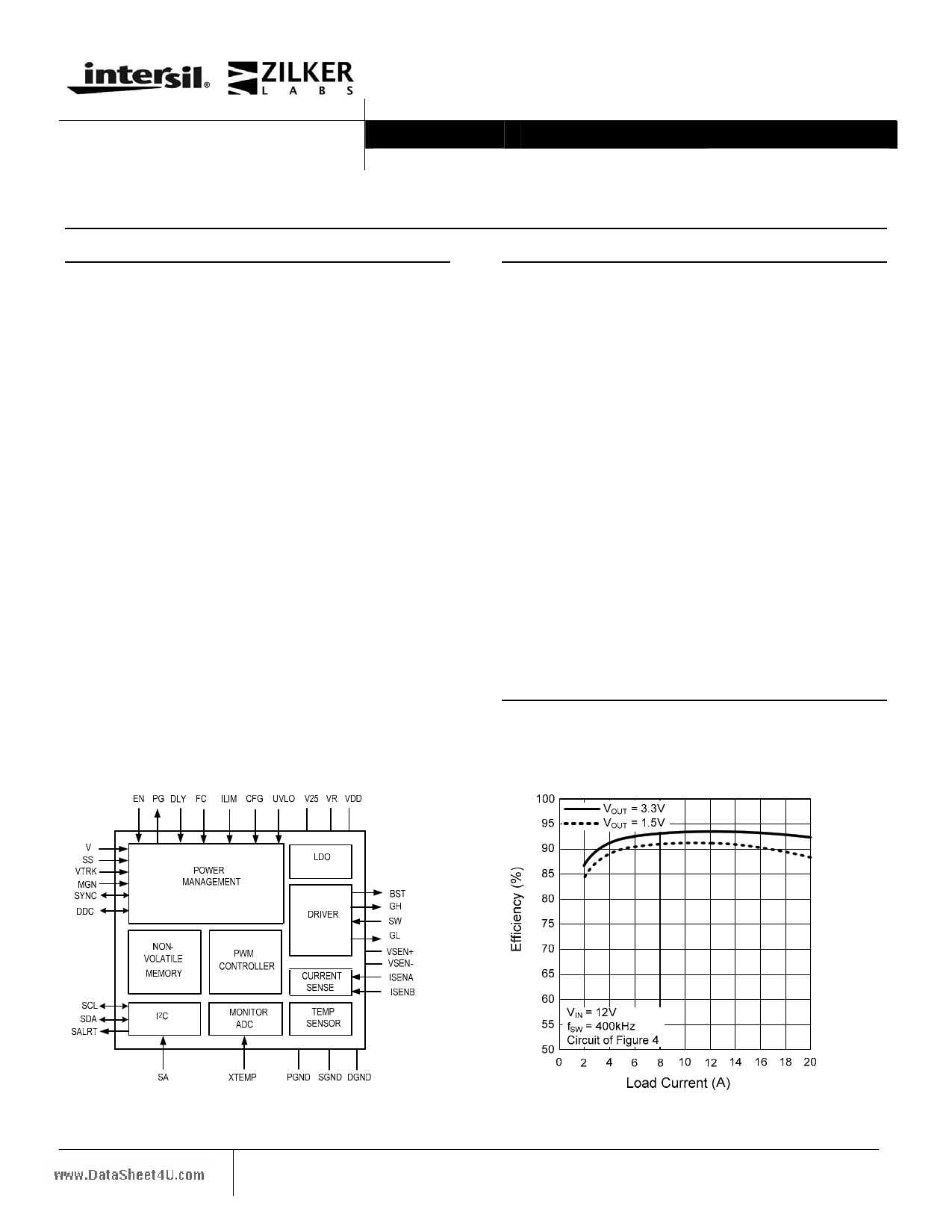
Figure 1. Block Diagram
1
Figure 2. Efficiency vs. Load Current
1-888-INTERSIL or 1-888-468-3774|Intersil (and design) is a registered trademark of Intersil Americas Inc.
Copyright © Intersil Americas Inc. 2009. All Rights Reserved
All other trademarks mentioned are the property of their respective owners
1 page 
ZL2006
www.DataSheet4U.com
Table 3. Electrical Characteristics (continued)
VDD = 12 V, TA = -40°C to 85°C unless otherwise noted. Typical values are at TA = 25°C.
Parameter
Conditions
Min Typ Max
Logic Input/Output Characteristics
Logic input bias current
EN,PG,SCL,SDA,SALRT pins
MGN input bias current
Logic input low, VIL
Logic input OPEN (N/C)
Multi-mode logic pins
Logic input high, VIH
Logic output low, VOL
Logic output high, VOH
IOL ≤ 4 mA
IOH ≥ -2 mA
- 10
-1
–
–
2.0
–
2.25
–
–
–
1.4
–
–
–
10
1
0.8
–
–
0.4
–
Oscillator and Switching Characteristics
Switching frequency range
Switching frequency set-point
accuracy
Predefined settings
(See Table 16)
200 – 1400
-5 –
5
Maximum PWM duty cycle
Minimum SYNC pulse width
Input clock frequency drift tolerance
Factory default
External clock source
95 –
150 –
- 13 –
–
–
13
Gate Drivers
High-side driver voltage
(VBST - VSW)
High-side driver peak gate drive
current (pull down)
(VBST - VSW) = 4.5 V
– 4.5 –
23–
High-side driver pull-up
resistance
High-side driver pull-down
resistance
Low-side driver peak gate drive
current (pull-up)
(VBST - VSW) = 4.5 V,
(VBST - VGH) = 50 mV
(VBST - VSW) = 4.5 V,
(VGH - VSW) = 50 mV
VR = 5 V
– 0.8 2
– 0.5 2
– 2.5 –
Low-side driver peak gate drive
current (pull-down)
VR = 5 V
– 1.8 –
Low-side driver pull-up
resistance
Low-side driver pull-down
resistance
Switching timing
GH rise and fall time
GL rise and fall time
Tracking
VTRK input bias current
VTRK tracking ramp accuracy
VTRK regulation accuracy
VR = 5 V,
(VR - VGL) = 50 mV
VR = 5 V,
(VGL - PGND) = 50 mV
(VBST - VSW) = 4.5 V,
CLOAD = 2.2 nF
VR = 5 V,
CLOAD = 2.2 nF
– 1.2 2
– 0.5 2
– 5 20
– 5 20
VTRK = 5.5 V
– 110 200
100% Tracking, VOUT - VTRK - 100 – + 100
100% Tracking, VOUT - VTRK
-1
–
1
Unit
µA
mA
V
V
V
V
V
kHz
%
%
ns
%
V
A
Ω
Ω
A
A
Ω
Ω
ns
ns
µA
mV
%
5 Data Sheet Revision 2/18/2009
www.intersil.com
5 Page 
ZL2006
4.2 Power Conversion Overview
> Input Voltage Bus
PG EN MGN ILIM(0,1) SS DLY(0,1) V(0,1) FC(0,1) VDD
VR
VTRK
SYNC
DDC
SALRT
I2C
SDA
SCL
SA(0,1)
Power Management
NVM
SYNC
GEN
Digital
Compensator
D-PWM
NLR
MOSFET
Drivers
BST
SW
PLL
REFCN
DAC
Communication
ADC
ADC
ADC
MUX
- VSEN
Σ
+ ISENB
ISENA
VDD
Voltage
Sensor
TEMP
Sensor
VSEN+
VSEN-
XTEMP
www.DataSheet4U.com
VOUT
Figure 5. ZL2006 Block Diagram
The ZL2006 operates as a voltage-mode, synchronous
buck converter with a selectable constant frequency
pulse width modulator (PWM) control scheme that
uses external MOSFETs, capacitors, and an inductor to
perform power conversion.
Figure 6. Synchronous Buck Converter
Figure 6 illustrates the basic synchronous buck
converter topology showing the primary power train
components. This converter is also called a step-down
converter, as the output voltage must always be lower
than the input voltage. In its most simple configuration,
the ZL2006 requires two external N-channel power
MOSFETs, one for the top control MOSFET (QH) and
one for the bottom synchronous MOSFET (QL). The
amount of time that QH is on as a fraction of the total
switching period is known as the duty cycle D, which
is described by the following equation:
D
≈
VOUT
VIN
During time D, QH is on and VIN – VOUT is applied
across the inductor. The current ramps up as shown in
Figure 7.
When QH turns off (time 1-D), the current flowing in
the inductor must continue to flow from the ground up
through QL, during which the current ramps down.
Since the output capacitor COUT exhibits a low
impedance at the switching frequency, the AC
component of the inductor current is filtered from the
output voltage so the load sees nearly a DC voltage.
11 Data Sheet Revision 2/18/2009
www.intersil.com
11 Page | ||
| Páginas | Total 45 Páginas | |
| PDF Descargar | [ Datasheet ZL2006.PDF ] | |
Hoja de datos destacado
| Número de pieza | Descripción | Fabricantes |
| ZL2004 | Adaptive Digital DC-DC Controller | Intersil Corporation |
| ZL2004-01 | Adaptive Digital DC-DC Controller | Intersil Corporation |
| ZL2005 | Digital-DC Integrated Power Management and Conversion IC | Intersil Corporation |
| ZL2005P | Digital-DC Controller | Intersil Corporation |
| Número de pieza | Descripción | Fabricantes |
| SLA6805M | High Voltage 3 phase Motor Driver IC. |
Sanken |
| SDC1742 | 12- and 14-Bit Hybrid Synchro / Resolver-to-Digital Converters. |
Analog Devices |
|
DataSheet.es es una pagina web que funciona como un repositorio de manuales o hoja de datos de muchos de los productos más populares, |
| DataSheet.es | 2020 | Privacy Policy | Contacto | Buscar |