|
|
|
PDF CK1100 Data sheet ( Hoja de datos )
| Número de pieza | CK1100 | |
| Descripción | OSCILLATOR BUILDING BLOCKS | |
| Fabricantes | ETC | |
| Logotipo | ||
Hay una vista previa y un enlace de descarga de CK1100 (archivo pdf) en la parte inferior de esta página. Total 2 Páginas | ||
|
No Preview Available !
CK1100 - OSCILLATOR BUILDING BLOCKS
Oscillators are everywhere in electronics. They are a basic
building block upon which the whole structure of
electronics and computers is based. This kit looks at the 3
basic types of multivibrators (MV). They are designed to
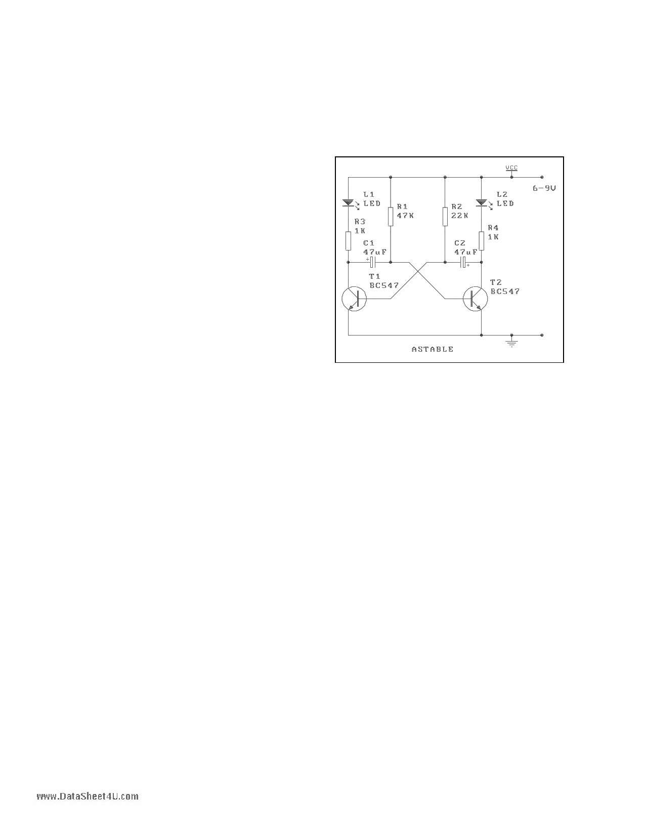
have zero, one or two stable states; the astable (the prefix
'a' means 'not') or free running MV, the monostable MV
(also called the one-shot) and the flip-flop or bistable ('bi'
means 2, bistable means 2 stable states.) In the flip-flop
MV a trigger pulse or control signal is required to change
from one state to the other. MV's use regenerative
(positive) feedback; the active components present within
the circuit operate as switches being alternately cutoff or
driven into saturation. These circuits have now largely
been replaced by timer ICs like the 555. (See Kit 111.)
However, a basic understanding of them is still essential
since they are still used in many circuits.
This kit builds each of these three circuits and allows you
to experiment with them. To understand how these circuits
work will also make sure you have an understanding of
resistors, capacitors, RC characteristics, the transistor as a
switch and the light emitting diode (LED).
ASSEMBLY INSTRUCTIONS
Components may be added to the PCB in any order. It is
usually easier to add the smallest height components, the
resistors, first. All the small-signal transistors are the same.
Solder a 1/2" (10mm) length of wire which has been cut
from the leads of the other components into the three holes
marked Trigger, Set and Reset. Add two flying leads to the
positive rail and to the negative rail using any spare
insulated wire you have in your junk box. You will use
these flying leads to touch the trigger, set & reset points to
see what effect they have on the operation of the MV's.
CIRCUIT DESCRIPTION
Most basic electronic text books give a review of these
three MV's. We suggest you use a text book as well as our
explanations below in order to get a good understanding of
these basic topics.
When the 9V battery is connected, the astable MV should
flash from one LED to the other. A diode on the input
protects the MV’s if the battery is connected wrongly. One
LED should be on for about twice the time of the other.
The LED in the monostable MV should remain off. In the
RS flip flop one LED should turn on and stay on. Play with
touching the flying wires to the trigger, set & reset points.
Try to follow what happens on the circuit diagram when
you touch a lead. What you see is all to do with transistors
acting as switches and capacitorscharging and discharging
with a time constant determined by an R and a C in the
charge path. You cannot do any harm to the components by
playing with the flying wires. If you have access to a CRO
look at the changes of the base/emitter voltages of the
transistors as you touch trigger, set & reset.
1. The Flip Flowpw.w.DataSheet4U.com
Computer memory elements (the group of circuit
components in a memory IC which stores each 'bit' - binary
digit) use the flip-flop principal. Play with the flying wires
onto the set and reset wires. You can very quickly see what
this circuit does; it remembers information about which
was the last LED to be make to be turned on or off. Of
course, you have to define a convention: which flying wire
you are using, which pin is called what, etc.
When the power is connected to the circuit one or other of
the two transistors will turn on. Both transistors will try to
turn on as the base of each tries to go high. But due to
slight differences in component values one will be quicker
than the other. Suppose it is T5. This means that T5
collector voltage is low (below .65V), which means that
the base of T6 is also low (since the two are connected)
and T6 is off. Now when the set lead is touched by the
positive rail, T6 is turned on because its base potential is
raised over 0.6V. So T6 turns on and its collector potential
drops which drops the base potential of T5 to below 0.65V
and so T5 turns off. The circuit has flipped into its other
state. Touch the reset with the positive lead and the circuit
flops back to T5 turned on again.
We called one LED the set, and the other reset but these
names are quite arbitrary. The flying negative lead also
causes the LED's to turn on and off but in the opposite way
to the sequence caused by the positive flying lead. Study
what is happening with the schematic in front of you.
2. The Monostable Multivibrator.
Now we introduce an RC network into the flip flop circuit
just described. An electrolytic capacitor replaces one of the
base bias resistors of the flip flop circuit. And the biasing
which was supplied by this resistor is provided by a 56K
resistor to the positive rail. When the power is turned on
the circuit will settle into a stable state in which T4 is on
and T3 is off. Use a multimeter to measure the base/emitter
and collector/emitter voltages of T3 & T4 to show this.
The capacitor will have about 6V across it. We have put on
1 page | ||
| Páginas | Total 2 Páginas | |
| PDF Descargar | [ Datasheet CK1100.PDF ] | |
Hoja de datos destacado
| Número de pieza | Descripción | Fabricantes |
| CK1100 | OSCILLATOR BUILDING BLOCKS | ETC |
| Número de pieza | Descripción | Fabricantes |
| SLA6805M | High Voltage 3 phase Motor Driver IC. |
Sanken |
| SDC1742 | 12- and 14-Bit Hybrid Synchro / Resolver-to-Digital Converters. |
Analog Devices |
|
DataSheet.es es una pagina web que funciona como un repositorio de manuales o hoja de datos de muchos de los productos más populares, |
| DataSheet.es | 2020 | Privacy Policy | Contacto | Buscar |