|
|
|
PDF PAM2701 Data sheet ( Hoja de datos )
| Número de pieza | PAM2701 | |
| Descripción | 4-Channel Regulated Charge Pump White LED Driver | |
| Fabricantes | Power Analog Micoelectronics | |
| Logotipo | ||
Hay una vista previa y un enlace de descarga de PAM2701 (archivo pdf) en la parte inferior de esta página. Total 14 Páginas | ||
|
No Preview Available !
PAM2701
4-Channel Regulated Charge Pump White LED Driver
Features
n Peak Efficiency: 90%
n Individual Current Regulation
n 3-bit Digital Output Control
n Two modes of operation:1x and 1.5x
n Current Matching with a Max Tolerance
of 3%
n Output Current up to 30mA per LED
n Total LED Current up to 4*30mA=120mA
n Fixed Frequency of 1MHz
n Open LED Protection
n Space Saving Package QFN 3mmx3mm
and QFN 4mmx4mm
n Pb-Free Package
Applications
n Cellular Phones
n LED Backlighting
n LCD Modules
n Handheld Devices
n Digital Cameras
n PDAs
n PMPs
n MP3 Players
Description
The PAM2701 is a 4-channel charge pump white
LED driver, capable of driving up to 4 LEDs in
parallel. The device operates in either 1x mode or
1.5x fractional mode, and it can switch from 1x
mode to 1.5x mode automatically when the input
voltage decreased. Its internal 4 current sink
regulators ensure both the LED current matching
and the brightness uniformity. The LED current
can be programmed by an external resistor, R ,SET
connected between the RSET pin and ground.
LED current of up to 30mA are supported by the
input supply voltage over a range of 2.7V to 5.5V,
making the device optimized for Li-Ion battery
applications.
The PAM2701 has a fixed switching frequency of
1MHz, allowing the use of very small value
ceramic capacitors. The enable input pin allows
the device to be set in shutdown mode, and the
current consumption is reduced to less than 1μA.
LED dimming can be done by several methods
including using a DC voltage to set the RSET pin
current, adding a switched resistor in parallel with
RSET, or applying a PWM signal to CTRx pin or EN
pin.
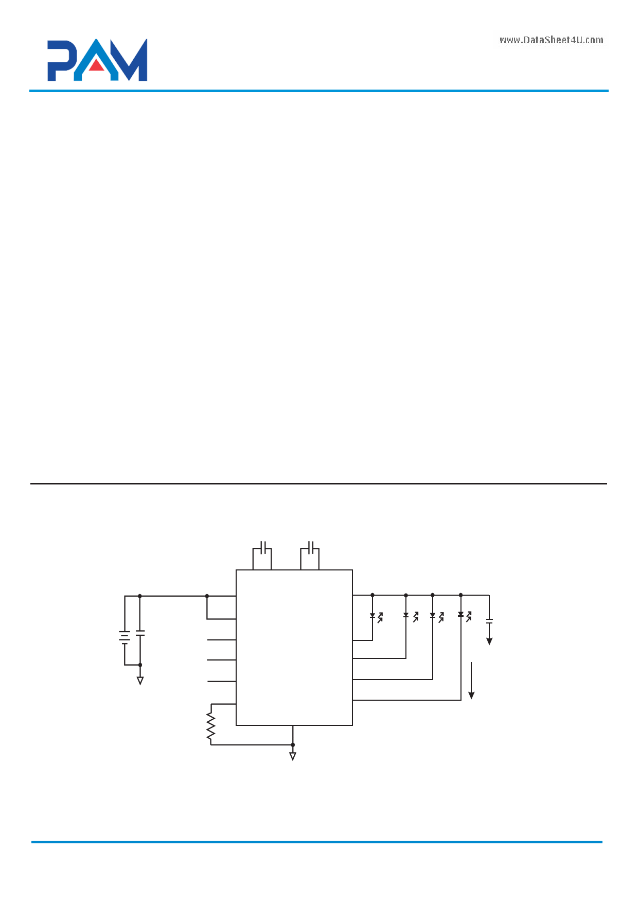
Typical Application
www.DataSheet4U.com
VIN
EN
CIN
1μF Control 0
Control 1
Control 2
RSET
24kΩ
1μF 1μF
8 9 11 10
C1+ C1- C2+ C2-
76
VIN
VOUT
1 EN PAM2701
2
CTR0
3
CTR1
4 CTR2
5 RSET
GND
LED1 16
15
LED2
14
LED3
13
LED4
12
Co
1μF
20mA
Power Analog Microelectronics,Inc
www.poweranalog.com
1
09/2008 Rev 1.3
1 page 
PAM2701
4-Channel Regulated Charge Pump White LED Driver
Electrical Characteristic
TA= 25°C, V =IN 3.5V, C =IN CO=1μF, unless otherwise noted.
Parameter
Input Voltage Range
Shutdown Current
Quiescent Current
RSET Regulated Voltage
Symbol
VIN
ISD
IQ
VRSET
Programmed LED Current
ILED
LED Current Accuracy
LED Channel Matching
ILED-A CC
ILED-DEV
Output Resistance (Open Loop) RO
Charge Pump Frequency
VIN at Mode Transition from 1x
to 1.5x
1x to 1.5x Mode Transition
Dropout Delay
Input Leakage Current
High Detect Threshold
Low Detect Threshold
fOSC
V IN -Tran
TDROP
IEN-CTR
V EN -CT RH
V EN-C T RL
Conditions
VEN=0V Shutdown Mode
1x Mode, No Load
1.5x Mode, No Load
RSET=90kΩ
RSET=29.3kΩ
RSET=14.7kΩ
(ILED-ILEDAVG)/ILEDAVG
1x Mode, IO=100mA
1.5x Mode, IO=100mA
ILED=15mA
ILED=20mA
On Inputs EN,CTR0,1&2
On Inputs EN,CTR0,1&2
On Inputs EN,CTR0,1&2
www.DataSheet4U.com
Min
2.7
1.19
1.5
Typ Max
5.5
0.05 1
0.6 1.2
2.5 5
1.23 1.25
5.0
15.0
30.0
±5
±3
1.7
4.3
1.0
3.45
3.60
10
1
0.4
Unit
V
μA
mA
mA
V
mA
mA
mA
%
%
Ω
Ω
MHz
V
V
μs
μA
V
V
Power Analog Microelectronics,Inc
www.poweranalog.com
5
09/2008 Rev 1.3
5 Page 
PAM2701
4-Channel Regulated Charge Pump White LED Driver
Application Information
PCB Layout
When the driver is in the 1.5X charge pump
mode, the 1MHz switching frequency operation
requires to minimize the trace length and
impedance to ground on all 4 capacitors. A
ground plane should cover the area on the
bottom side of the PCB opposite to the IC and the
bypass capacitors. Capacitors CIN and Co should
be short connected to ground with multiple vias
as shown on Figure4.
Square copper area matches the QFN 16
exposed pad (GND) which is connected by a
trace to the pin 12 pad (GND). A large via
(metalized hole) centered in the square pad
provides a low impedance connection to the
ground plane on the opposite side of the PCB and
allows the heat dissipation of the LED driver to
achieve excellent thermal performance.
Figure 4: PCB layout
www.DataSheet4U.com
Power Analog Microelectronics,Inc
www.poweranalog.com
11
09/2008 Rev 1.3
11 Page | ||
| Páginas | Total 14 Páginas | |
| PDF Descargar | [ Datasheet PAM2701.PDF ] | |
Hoja de datos destacado
| Número de pieza | Descripción | Fabricantes |
| PAM2701 | 4-Channel Regulated Charge Pump White LED Driver | Power Analog Micoelectronics |
| Número de pieza | Descripción | Fabricantes |
| SLA6805M | High Voltage 3 phase Motor Driver IC. |
Sanken |
| SDC1742 | 12- and 14-Bit Hybrid Synchro / Resolver-to-Digital Converters. |
Analog Devices |
|
DataSheet.es es una pagina web que funciona como un repositorio de manuales o hoja de datos de muchos de los productos más populares, |
| DataSheet.es | 2020 | Privacy Policy | Contacto | Buscar |