|
|
|
PDF L5988D Data sheet ( Hoja de datos )
| Número de pieza | L5988D | |
| Descripción | 4A continuous (more than 5 A pulsed) step-down switching regulator | |
| Fabricantes | ST Microelectronics | |
| Logotipo | ||
Hay una vista previa y un enlace de descarga de L5988D (archivo pdf) en la parte inferior de esta página. Total 53 Páginas | ||
|
No Preview Available !
www.DataSheet4U.com
L5988D
4 A continuous (more than 5 A pulsed) step-down switching
regulator with synchronous rectification
Preliminary Data
Features
I 4 A output current (more than 5 pulsed)
I Operating input voltage from 2.9 V to 18 V
I External 1.8 V ± 2 % reference voltage
I Output voltage from 0.6 to input voltage
I MLCC compatible
I 200 ns TON
I Programmable UVLO matches 3.3 V, 5 V and
12 V bus
I FSW programmable up to 1 MHz
I Voltage feed-forward
I Zero-load current operation
I Programmable current limit on both switches
I Programmable sink current capability
I Pre-bias start up capability
I Thermal shutdown
HTSSOP 16
Applications
I Consumer: STB, DVD, LCD TV, VCR, car
radio, LCD monitors
I Networking: XDSL, modems, routers and
switches
I Computer and peripherals: printers, audio /
graphic cards, optical storage, hard disk drive
I Industrial: DC-DC modules, factory automation
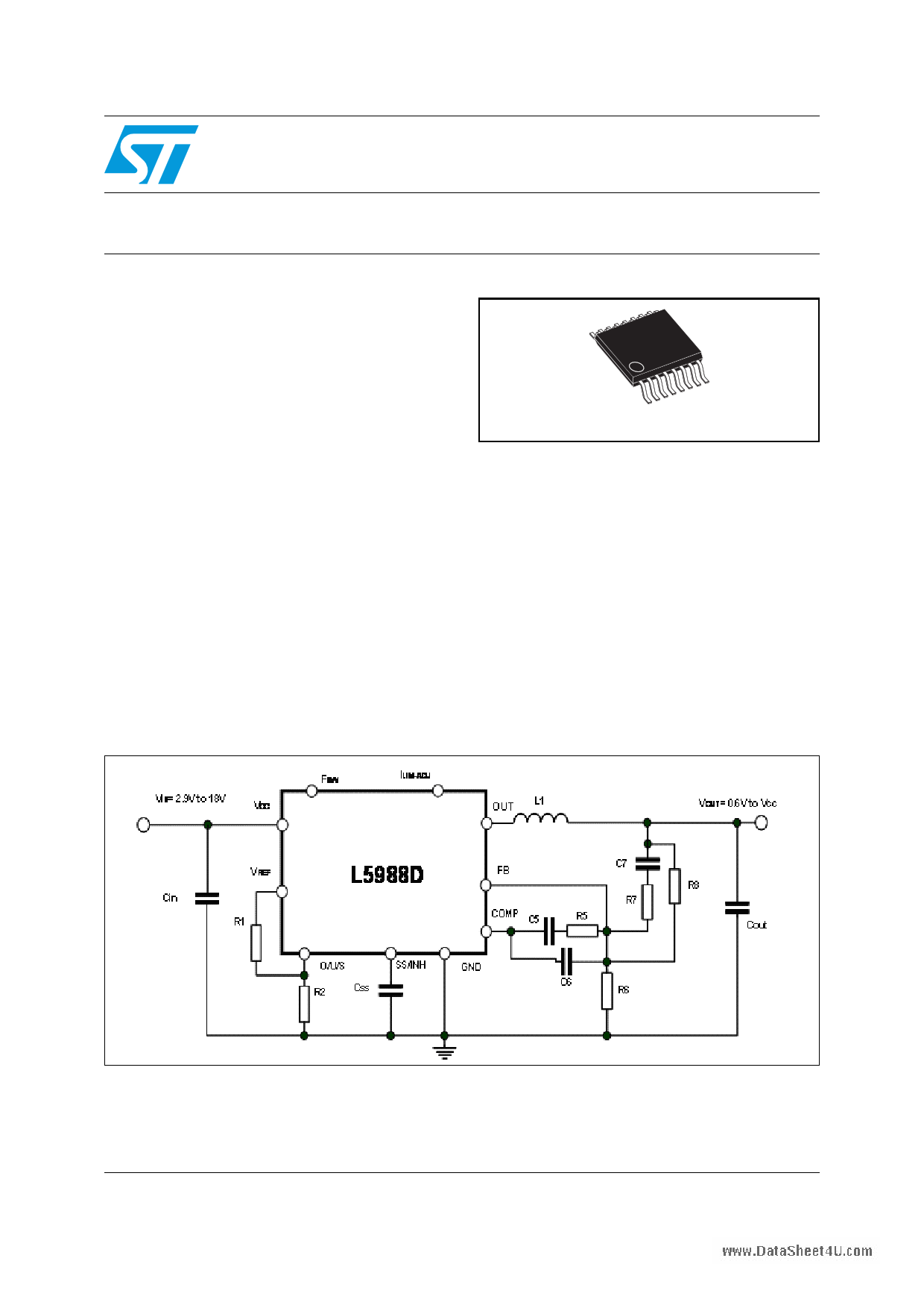
Figure 1. Test application circuit
January 2009
Rev 1
This is preliminary information on a new product now in development or undergoing evaluation.
Details are subject to change without notice.
1/53
www.st.com
53
1 page 
www.DataSLh5e9et848UD.com
List of figures
List of figures
Figure 1.
Figure 2.
Figure 3.
Figure 4.
Figure 5.
Figure 6.
Figure 7.
Figure 8.
Figure 9.
Figure 10.
Figure 11.
Figure 12.
Figure 13.
Figure 14.
Figure 15.
Figure 16.
Figure 17.
Figure 18.
Figure 19.
Figure 20.
Figure 21.
Figure 22.
Figure 23.
Figure 24.
Figure 25.
Figure 26.
Figure 27.
Figure 28.
Figure 29.
Figure 30.
Figure 31.
Figure 32.
Figure 33.
Figure 34.
Figure 35.
Figure 36.
Figure 37.
Figure 38.
Figure 39.
Figure 40.
Figure 41.
Test application circuit . . . . . . . . . . . . . . . . . . . . . . . . . . . . . . . . . . . . . . . . . . . . . . . . . . . . . 1
Pin connection . . . . . . . . . . . . . . . . . . . . . . . . . . . . . . . . . . . . . . . . . . . . . . . . . . . . . . . . . . . 7
Voltage mode control loop . . . . . . . . . . . . . . . . . . . . . . . . . . . . . . . . . . . . . . . . . . . . . . . . . 12
Internal block diagram . . . . . . . . . . . . . . . . . . . . . . . . . . . . . . . . . . . . . . . . . . . . . . . . . . . . 12
Oscillator circuit block diagram . . . . . . . . . . . . . . . . . . . . . . . . . . . . . . . . . . . . . . . . . . . . . . 15
Sawtooth: voltage feed forward . . . . . . . . . . . . . . . . . . . . . . . . . . . . . . . . . . . . . . . . . . . . . 16
Sawtooth: synchronization and frequency adjust . . . . . . . . . . . . . . . . . . . . . . . . . . . . . . . . 16
Input RMS current of two synchronized regulators . . . . . . . . . . . . . . . . . . . . . . . . . . . . . . . 17
OVP not latched . . . . . . . . . . . . . . . . . . . . . . . . . . . . . . . . . . . . . . . . . . . . . . . . . . . . . . . . . 19
OVP latched . . . . . . . . . . . . . . . . . . . . . . . . . . . . . . . . . . . . . . . . . . . . . . . . . . . . . . . . . . . . 20
constant current protection at extreme duty cycles . . . . . . . . . . . . . . . . . . . . . . . . . . . . . . 22
minimum TON. . . . . . . . . . . . . . . . . . . . . . . . . . . . . . . . . . . . . . . . . . . . . . . . . . . . . . . . . . . 23
Type III compensation network . . . . . . . . . . . . . . . . . . . . . . . . . . . . . . . . . . . . . . . . . . . . . . 30
Open loop gain: module bode diagram. . . . . . . . . . . . . . . . . . . . . . . . . . . . . . . . . . . . . . . . 30
Open loop gain bode diagram with ceramic output capacitor . . . . . . . . . . . . . . . . . . . . . . . 32
Type II compensation network . . . . . . . . . . . . . . . . . . . . . . . . . . . . . . . . . . . . . . . . . . . . . . 33
Open loop gain: module bode diagram. . . . . . . . . . . . . . . . . . . . . . . . . . . . . . . . . . . . . . . . 33
Open loop gain bode diagram with high ESR output capacitor . . . . . . . . . . . . . . . . . . . . . 35
Maximum continuos output current vs. duty cycle . . . . . . . . . . . . . . . . . . . . . . . . . . . . . . . 36
Switching losses . . . . . . . . . . . . . . . . . . . . . . . . . . . . . . . . . . . . . . . . . . . . . . . . . . . . . . . . . 37
Estimation of the internal power losses (VIN = 12 V, VOUT = 1.2 V, fSW = 400 kHz) . . . . . 38
Estimation of the internal power losses (VIN = 5 V, VOUT = 1.2 V, fSW = 400 kHz) . . . . . . 39
Measurement of the thermal impedance of the evaluation board. . . . . . . . . . . . . . . . . . . . 40
Top board layout . . . . . . . . . . . . . . . . . . . . . . . . . . . . . . . . . . . . . . . . . . . . . . . . . . . . . . . . . 41
Bottom board layout . . . . . . . . . . . . . . . . . . . . . . . . . . . . . . . . . . . . . . . . . . . . . . . . . . . . . . 42
Demonstration board application circuit (fSW = 400 kHz) . . . . . . . . . . . . . . . . . . . . . . . . . . 42
Demonstration board application circuit (fSW = 600 kHz) . . . . . . . . . . . . . . . . . . . . . . . . . . 43
Junction temperature vs. fSW at VIN = 12 V, VOUT = 3.3 V . . . . . . . . . . . . . . . . . . . . . . . . . 45
Junction temperature vs. fSW at VIN = 5 V, VOUT = 3.3 V . . . . . . . . . . . . . . . . . . . . . . . . . . 45
Junction temperature vs. fSW at VIN = 3.3 V, VOUT = 1.2 V . . . . . . . . . . . . . . . . . . . . . . . . 45
Junction temperature vs. VOUT at VIN = 12 V, fSW = 400 kHz . . . . . . . . . . . . . . . . . . . . . . 45
Junction temperature vs. VOUT at VIN = 5 V, fSW = 400 kHz . . . . . . . . . . . . . . . . . . . . . . . 46
Junction temperature vs. VOUT at VIN = 3.3 V, fSW = 400 kHz . . . . . . . . . . . . . . . . . . . . . . 46
Efficiency vs. output current at VIN = 3.3 V, fSW = 400 kHz . . . . . . . . . . . . . . . . . . . . . . . . 46
Efficiency vs. output current at VIN = 5 V, fSW = 250 kHz . . . . . . . . . . . . . . . . . . . . . . . . . . 46
Efficiency vs. output current . . . . . . . . . . . . . . . . . . . . . . . . . . . . . . . . . . . . . . . . . . . . . . . . 47
Load regulation . . . . . . . . . . . . . . . . . . . . . . . . . . . . . . . . . . . . . . . . . . . . . . . . . . . . . . . . . . 47
Line regulation . . . . . . . . . . . . . . . . . . . . . . . . . . . . . . . . . . . . . . . . . . . . . . . . . . . . . . . . . . 47
Load transient from 0 to 3 A . . . . . . . . . . . . . . . . . . . . . . . . . . . . . . . . . . . . . . . . . . . . . . . . 47
Soft-start . . . . . . . . . . . . . . . . . . . . . . . . . . . . . . . . . . . . . . . . . . . . . . . . . . . . . . . . . . . . . . . 47
HTSSOP16 mechanical drawing . . . . . . . . . . . . . . . . . . . . . . . . . . . . . . . . . . . . . . . . . . . . 49
5/53
5 Page 
www.DataSLh5e9et848UD.com
Electrical characteristics
Table 4. Electrical characteristic (continued)
Symbol
Parameter
Test condition
Min Typ Max Unit
- UVLO 3.3 V bus
TH4 - OVP latched
- Sink
- UVLO 12 V bus
TH5 - OVP not latched
- No sink
- UVLO 12 V bus
TH6 - OVP not latched
- Sink
- UVLO 12 V bus
TH7 - OVP latched
- No sink
- UVLO 12 V bus
TH8 - OVP latched
- Sink
(3) 0.71
(3) 0.93
(3) 1.16
(3) 1.385
(3) 1.615
0.875 V
1.085 V
1.31 V
1.525 V
VREF V
1. Specification over the junction temperature range (TJ) of -40 to +125 °C are guaranteed by design,
characterization and statistical correlation
2. Guaranteed by design
3. VCC = 4 V
11/53
11 Page | ||
| Páginas | Total 53 Páginas | |
| PDF Descargar | [ Datasheet L5988D.PDF ] | |
Hoja de datos destacado
| Número de pieza | Descripción | Fabricantes |
| L5988 | 4A step-down switching regulator | STMicroelectronics |
| L5988D | 4A continuous (more than 5 A pulsed) step-down switching regulator | ST Microelectronics |
| Número de pieza | Descripción | Fabricantes |
| SLA6805M | High Voltage 3 phase Motor Driver IC. |
Sanken |
| SDC1742 | 12- and 14-Bit Hybrid Synchro / Resolver-to-Digital Converters. |
Analog Devices |
|
DataSheet.es es una pagina web que funciona como un repositorio de manuales o hoja de datos de muchos de los productos más populares, |
| DataSheet.es | 2020 | Privacy Policy | Contacto | Buscar |