|
|
|
PDF NJM2517 Data sheet ( Hoja de datos )
| Número de pieza | NJM2517 | |
| Descripción | Signal Processor for TFT Display / QFP48-R2 | |
| Fabricantes | JRC | |
| Logotipo | ||
Hay una vista previa y un enlace de descarga de NJM2517 (archivo pdf) en la parte inferior de esta página. Total 27 Páginas | ||
|
No Preview Available !
www.DataSheet4U.com
NJM2517
COLOR TFT SIGNAL PROCESSOR RGB INTERFACE IC
s GENERAL DESCRIPTION
The NJM2517 is a RGB Interface for color TFT signal processor.
It contains all function, like as RGB interface, synchronous
separate circuit, side-black control circuit, and common pole driver,
required by color TFT signal processing.
s FEATURES
q NTSC/PAL matching
q Internal two systems input for analog RGB
q Internal synchronous separate circuit
q Internal black level insertion circuit (Use for aspect ratio change)
q Internal Gamma 2-point correction circuit
q Internal Color TFT Common Pole Driver
q Bipolar technology
q Package Outline QFP48-R2(7.0X7.0mm 0.5mmpitch)
s PACKAGE OUTLINE
NJM2517FR2
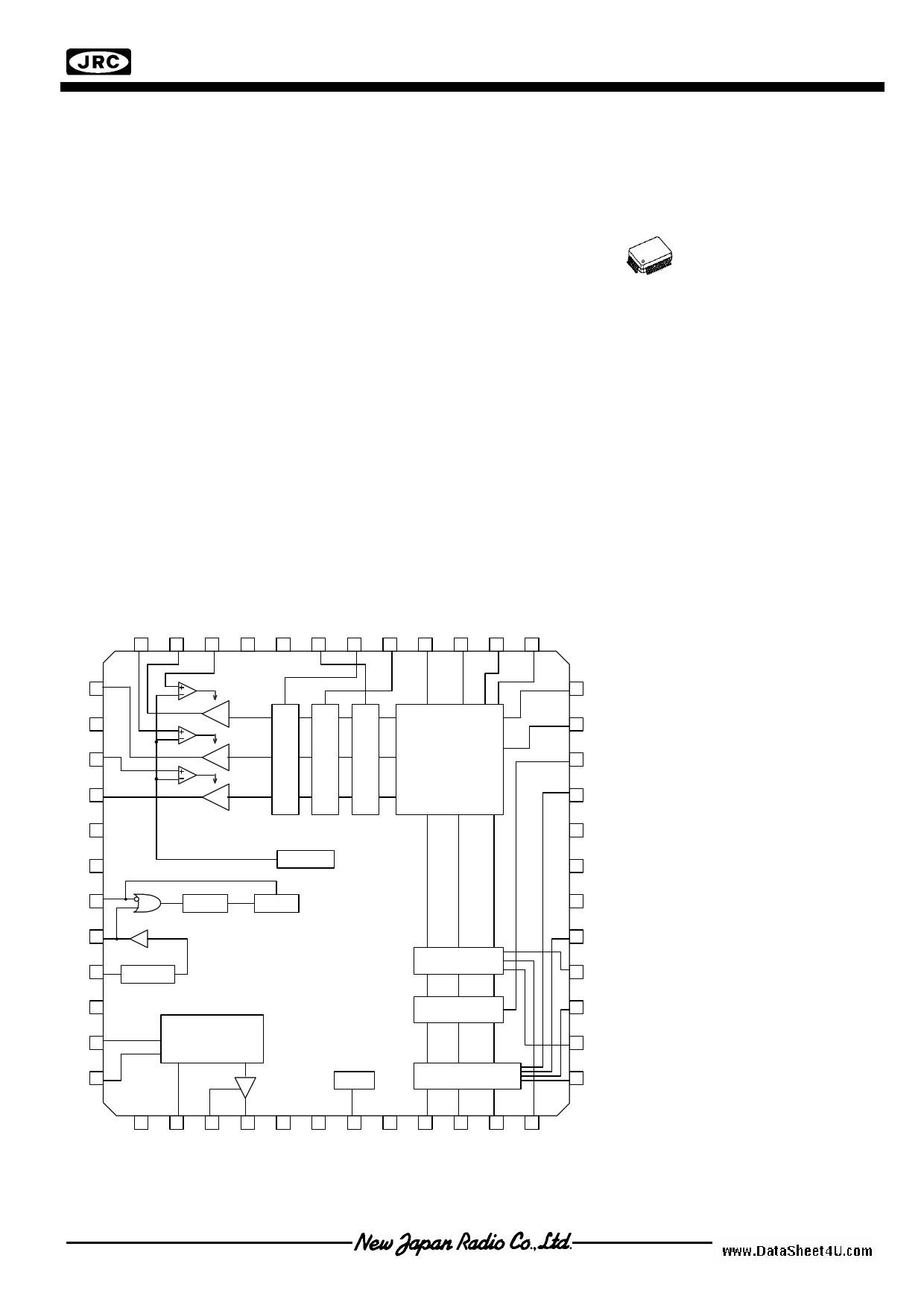
s BLOCK DIAGRAM
48 47 46 45 44 43 42 41 40 39 38 37
GOUT 1
GND2 2
BDET 3
BOUT 4
NC 5
GND1 6
1/2*VCC2
HSYIN 7
SYNCOUT 8
CPGEN
MASK
SYNCIN 9
SYNCSEP
NC 10
VCOMAMP 11
VCOM DRIVER
VCOMIN 12
REG
GAMMA
CORRECT
CLAMP
CONTRAST
RGB in1 / RGB in2
SW
13 14 15 16 17 18 19 20 21 22 23 24
s PIN CONFIGURATION
1 . GOUT
25.BIN 1
2 . GND2
26.GACLAMPG
3 . BDET
27.RIN 2
36 VG2
4 . BOUT
28.GACLAMPB
5 . NC
29.GIN 2
35 VG1
6 . GND1
30.NC
7 . HSYIN
34 CONTRAST 8 . SYNCOUT
31.VCC1
32.NC
33 BIN2
9 . SYNCIN
10.NC
33.BIN 2
34.CONTRAST
32 NC
11.VCOMAMP
12.VCOMIN
35.VG1
36.VG2
31 VCC1
13.VCC3
14.VCOMCENT
37.SUBVG1R
38.SUBVG1B
30 NC
15.VCOMFB
16.VCOMOUT
39.SUBVG2R
40.SUBVG2B
29 GIN2
17.VEE1
18.IREF
41.BRIGHT
42.FRP
28 GACLAMPB 19.REGOUT
20.GND3
43.SIDEBLACK
44.NC
27 RIN2
21.RIN 1
45.VCC2
22.SW
46.RDET
26 GACLAMPG 23.GIN 1
47.ROUT
24.GACLAMPR
48.GDET
25 BIN1
Ver.5
-1-
1 page 
www.DataSheet4U.com
NJM2517
s ELECTRICAL CHARACTERISTICS (Ta=25°C,VCC1=5V, VCC2=5V,VCC3=7V,VEE1=-5V)
PARAMETER
SYMBOL
TEST CONDITION (TP=IC Pin No.)
MIN.
Synchronous Separate
Output Turn OFF Time
Synchronous Separate
Output Turn OFF Time
ttHL SG2 applied to TP9.Then measure
time difference of 20% to 80% swing
ttLH level of TP8.
-
-
External Synchronous
Input Timing 1
t1
Sync Separate Output
3.0
TYP.
0.2
0.2
-
MAX.
-
-
-
UNIT
µs
External Synchronous
Input Timing 2
External Synchronous
Input Timing 3
RGB Output
Delay Time 1
RGB Output
Delay Time 2
t2
t3
tPHL1
tPHL2
t1
External Sync Input
t3
t2
2.0
1.6
SG2 applied to TP9, SG8 applied to
TP7, TP22=0V, SG4 (0.35Vpp) applied
to TP21, TP23, TP25. Then measure
time difference of 50% swing level of
TP21 and TP47,TP23 and TP1, TP25
and TP4
tPHL1=turn ON
tPHL2=turn OFF
-
-
-
2.0
0.1
0.1
-
2.4
-
-
Crosstalk Among RGB
CTRGB1
CTRGB2
CTRGB3
SG2 applied to TP9, SG8 applied to
TP7, TP22=0V,
TP42=H, TP23= TP25=GND, SG3
(1MHz, 700mVpp) applied to TP21.
Measure the output of 1MHz
component on TP47, TP1 and TP4.
Calculate the swing ratio of TP1,
TP4 toward TP47.
SG2 applied to TP9, SG8 applied to
TP7, TP22=0V,
TP42=H, TP21= TP25=GND, SG3
(1MHz, 700mVpp) applied to TP23.
Measure the output of 1MHz
component on TP47, TP1 and TP4.
Calculate the swing ratio of TP47,
TP4 toward TP1.
SG2 applied to TP9, SG8 applied to
TP7, TP22=0V,
TP42=H, TP21=TP23=GND, SG3
(1MHz, 700mVpp) applied to TP25.
Measure the output of 1MHz
component on TP47, TP1 and TP4.
Calculate the swing ratio of TP47,
TP1 toward TP4.
- -50 -40
- -50 -40
- -50 -40
µs
µs
dB
Ver.5
-5-
5 Page 
www.DataSheet4U.com
s INPUT SIGNAL
SYMBOL
INPUT SIGNAL
Turn ON, Turn OFF Signal under 50ns
SG6
SG7
1H
FRP Signal of inverting Every 1H
1H
NJM2517
5V
5Vp-p
0V
5V
5Vp-p
0V
SG8
Horizontal Sync. Signal Synchronous to SG2
4.7uS
1H
t1
SW Signal Synchronous to SG2
4.7uS
286mVp-p SG2
t3=2uS(typ)
t2=5uS(typ)
2.0V
0.8V
SG11
SG9
1H
286mVp-p SG2
5Vp-p SG12
SG10
4.7uS
Signal Synchronous to SG2
10uS<
110mV
110mV
Pulse Width (same as SG12)
286mVp-p SG2
Signal Level 2
Signal Level 1
SG13
Ver.5
- 11 -
11 Page | ||
| Páginas | Total 27 Páginas | |
| PDF Descargar | [ Datasheet NJM2517.PDF ] | |
Hoja de datos destacado
| Número de pieza | Descripción | Fabricantes |
| NJM2512 | AC-Coupling Capacitor Low Voltage Video Driver | New Japan Radio |
| NJM2512A | 47uF AC-Coupling Capacitor Low Voltage Video Driver | NJR |
| NJM2513 | 3-INPUT/2-INPUT VIDEO SWITCH | New Japan Radio |
| NJM2515 | Video Amplifier / SSOP32 | JRC |
| Número de pieza | Descripción | Fabricantes |
| SLA6805M | High Voltage 3 phase Motor Driver IC. |
Sanken |
| SDC1742 | 12- and 14-Bit Hybrid Synchro / Resolver-to-Digital Converters. |
Analog Devices |
|
DataSheet.es es una pagina web que funciona como un repositorio de manuales o hoja de datos de muchos de los productos más populares, |
| DataSheet.es | 2020 | Privacy Policy | Contacto | Buscar |