|
|
|
PDF PE43701 Data sheet ( Hoja de datos )
| Número de pieza | PE43701 | |
| Descripción | RF Digital Attenuator 7-bit | |
| Fabricantes | Peregrine Semiconductor | |
| Logotipo | ||
Hay una vista previa y un enlace de descarga de PE43701 (archivo pdf) en la parte inferior de esta página. Total 13 Páginas | ||
|
No Preview Available !
Product Description
wwTwh.deataPshEe4et347u.0co1mis a HaRP™-enhanced, high linearity, 7-bit RF
Digital Step Attenuator (DSA). This highly versatile DSA
covers a 31.75 dB attenuation range in 0.25 dB steps. The
Peregrine 50Ω RF DSA provides a parallel or serial-
addressable CMOS control interface. It maintains high
attenuation accuracy over frequency and temperature and
exhibits very low insertion loss and low power consumption.
Performance does not change with Vdd due to on-board
regulator. This next generation Peregrine DSA is available in a
5x5 mm 32-lead QFN footprint.
The PE43701 is manufactured on Peregrine’s UltraCMOS™
process, a patented variation of silicon-on-insulator (SOI)
technology on a sapphire substrate, offering the performance
of GaAs with the economy and integration of conventional
CMOS.
Figure 1. Package Type
32-lead 5x5x0.85 mm QFN Package
Product Specification
PE43701
50 Ω RF Digital Attenuator
7-bit, 31.75 dB, DC-4.0 GHz
Features
• HaRP™-enhanced UltraCMOS™ device
• Attenuation: 0.25 dB steps to 31.75 dB
• High Linearity: Typical +59 dBm IIP3
• Excellent low-frequency performance
• 3.3 V or 5.0 V Power Supply Voltage
• Fast switch settling time
• Programming Modes:
• Direct Parallel
• Latched Parallel
• Serial-Addressable: Program up to
eight addresses 000 - 111
• High-attenuation state @ power-up (PUP)
• CMOS Compatible
• No DC blocking capacitors required
• Packaged in a 32-lead 5x5x0.85 mm QFN
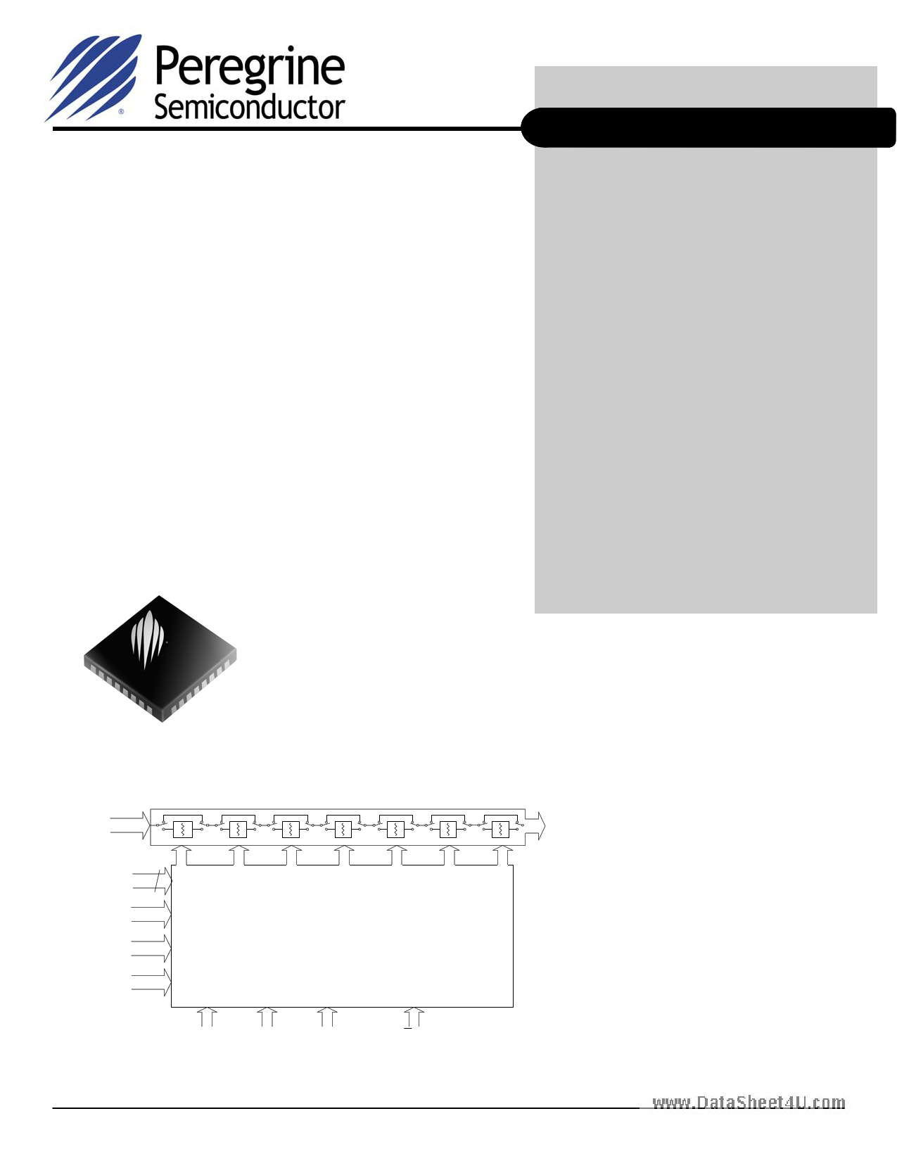
Figure 2. Functional Schematic Diagram
RF Input
Switched Attenuator Array
Parallel Control 7
Serial In
CLK
LE
A0
Control Logic Interface
A1 A2
P/S
Document No. 70-0243-04 │ www.psemi.com
RF Output
©2008-2009 Peregrine Semiconductor Corp. All rights reserved.
Page 1 of 13
1 page 
PE43701
Product Specification
Figure 18. Pin Configuration (Top View)
www.datasheet4u32.co3m1 30 29 28 27 26 25
NC
VDD
P/S
A0
GND
GND
RF1
GND
1
2
3
4
5
6
7
8
Exposed
Solder pad
9 10 11 12 13 14 15 16
24 CLK
23 LE
22 A1
21 A2
20 GND
19 GND
18 RF2
17 GND
Table 2. Pin Descriptions
Pin No. Pin Name
Description
1 N/C No Connect
2 VDD Power supply pin
3 P/S Serial/Parallel mode select
4 A0 Address Bit A0 (LSB)
5, 6, 8-17,
19, 20
GND
Ground
7 RF1 RF1 port
18 RF2 RF2 port
21 A2 Address Bit A2
22 A1 Address Bit A1
23 LE Latch Enable input
24
CLK
Serial interface clock input
25 SI Serial Interface input
26 C16 Attenuation control bit, 16 dB
27 C8 Attenuation control bit, 8 dB
28 C4 Attenuation control bit, 4 dB
29 C2 Attenuation control bit, 2 dB
30 C1 Attenuation control bit, 1 dB
31
C0.5
Attenuation control bit, 0.5 dB
32
C0.25
Attenuation control bit, 0.25 dB
Paddle
GND
Ground for proper operation
Document No. 70-0243-04 │ www.psemi.com
Electrostatic Discharge (ESD) Precautions
When handling this UltraCMOS™ device, observe the
same precautions that you would use with other ESD-
sensitive devices. Although this device contains
circuitry to protect it from damage due to ESD,
precautions should be taken to avoid exceeding the
specified rating.
Latch-Up Avoidance
Unlike conventional CMOS devices, UltraCMOS™
devices are immune to latch-up.
Moisture Sensitivity Level
The Moisture Sensitivity Level rating for the PE43701 in
the 5x5 QFN package is MSL1.
Switching Frequency
The PE43701 has a maximum 25 kHz switching rate.
Switching rate is defined to be the speed at which the
DSA can be toggled across attenuation states.
Exposed Solder Pad Connection
The exposed solder pad on the bottom of the package
must be grounded for proper device operation.
©2008-2009 Peregrine Semiconductor Corp. All rights reserved.
Page 5 of 13
5 Page 
PE43701
Product Specification
Figure 23. Evaluation Board Schematic
Peregrine Specification 102-0381
www.datasheet4u.com
Figure 24. Package Drawing
Note: Capacitors C1-C8, C13, & C14 may be omitted.
QFN 5x5 mm
MAX
A NOM
0.900
0.850
MIN 0.800
Document No. 70-0243-04 │ www.psemi.com
©2008-2009 Peregrine Semiconductor Corp. All rights reserved.
Page 11 of 13
11 Page | ||
| Páginas | Total 13 Páginas | |
| PDF Descargar | [ Datasheet PE43701.PDF ] | |
Hoja de datos destacado
| Número de pieza | Descripción | Fabricantes |
| PE43701 | RF Digital Attenuator 7-bit | Peregrine Semiconductor |
| PE43701 | (PE43x0x) 5-bit RF Digital Attenuator | Peregrine Semiconductor |
| PE43702 | RF Digital Attenuator 7-bit | Peregrine Semiconductor |
| PE43702 | (PE43x0x) 5-bit RF Digital Attenuator | Peregrine Semiconductor |
| Número de pieza | Descripción | Fabricantes |
| SLA6805M | High Voltage 3 phase Motor Driver IC. |
Sanken |
| SDC1742 | 12- and 14-Bit Hybrid Synchro / Resolver-to-Digital Converters. |
Analog Devices |
|
DataSheet.es es una pagina web que funciona como un repositorio de manuales o hoja de datos de muchos de los productos más populares, |
| DataSheet.es | 2020 | Privacy Policy | Contacto | Buscar |