|
|
|
PDF XC9221 Data sheet ( Hoja de datos )
| Número de pieza | XC9221 | |
| Descripción | (XC9220 / XC9221) Step-Down DC/DC Controller ICs | |
| Fabricantes | Torex Semiconductor | |
| Logotipo | ||
Hay una vista previa y un enlace de descarga de XC9221 (archivo pdf) en la parte inferior de esta página. Total 22 Páginas | ||
|
No Preview Available !
XC9220/XC9221 Series
16V Input Voltage, Step-Down DC/DC Controller ICs.
ETR0511_007
www.datasheet4u.com
GENERAL DESCRIPTION
The XC9220/XC9221 series is a group of multi-purpose step-down DC/DC controller ICs. The ICs enable a high efficiency,
stable power supply with an output current up to 3A to be configured using only a transistor, a coil, a diode, and two capacitors
connected externally. Low ESR capacitors such as a ceramic capacitor can be used as an output capacitor.
The XC9220/XC9221 series has a 0.9V (±1.5%) reference voltage, and using externally connected resistors, the output
voltage can be set freely. With an internal switching frequency of 300kHz and 500kHz 1.0MHz, small external components
can also be used. The XC9220 series is PWM control, and the XC9221 series is PWM/PFM mode, which automatically
switches from PWM to PFM during light loads and high efficiencies can be achieved over a wide range of load conditions.
As for the soft-start time, the XC9220/XC9221A and C series is internally set to 4msec and the XC9220/XC9221B and D
series can be externally set-up. With the built-in U.V.L.O. (Under Voltage Lock Out) function, the internal P-channel driver
transistor is forced OFF when input voltage becomes 2.3V or lower.
APPLICATIONS
Set top boxes
Digital TVs
DVD/HDD recorders
Portable information terminals
Notebook computers
FEATURES
Operating Voltage Range : 2.8V ~ 16.0V
Output Voltage Range
: 1.2V or more
Output Voltage Externally Set : 0.9V (accuracy +1.5%)
Output Current
: Less than 3.0A
Oscillation Frequency
: 300kHz, 500kHz, and 1.0MHz
Control Methods
: PWM control (XC9220)
PWM/PFM automatic switching
(XC9221)
Soft-Start Function
: 4ms, internally set
(XC9220/XC9221A, 500kHz)
Protection Circuits
Externally set (XC9220/XC9221B)
: Integral protection (1.0 ms)
(XC9220/XC9221 Aand B series)
Short-circuit protection
Low ESR
Capacitor Compatible
Packages
: Ceramic capacitor
: SOT-25
USP-6C
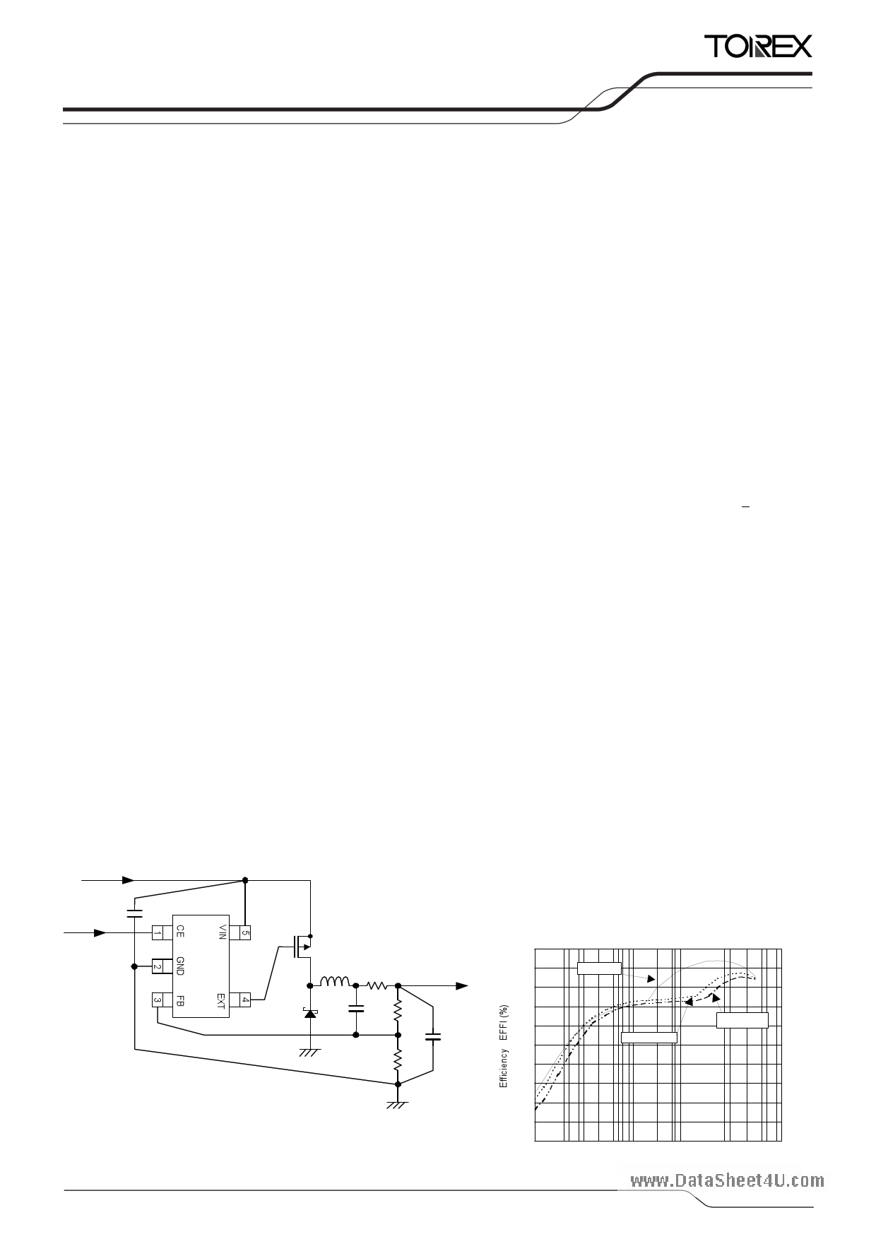
TYPICAL APPLICATION CIRCUIT
V IN
TYPICAL PERFORMANCE
CHARACTERISTICS
Efficiency vs. Output Current
CIN
CE
Pc h
MOSFET
RS ENS E
L ( f or ceramic CL )
VOUT
SBD
CFB
RFB1
RFB2
CL
* RSENSE : Tantalum and electrolytic capacitors can be used, in w hich case,
RSENSE becomes unnecessary.
XC9221A095MR (VOUT=3.3V, FOSC=500kHz)
CIN=47 F (OS-Con), CL=47 F (OS-Con),
L=10 H (CDRH8D43, SUMIDA)
PchMOSFET: CPH3308 (SANYO), CDD=1.0 F (ceramic), RIN=10
100
90 VIN=5.0V
80
70
60 VIN=16.0V
50 VIN=12.0V
40
30
20
10
0
0.1
1 10 100 1000
Output Current IOUT (mA)
10000
1/22
1 page 
XC9220/XC9221
Series
ELECTRICAL CHARACTERISTICS (Continued)
XC9220/XC9221 B and D series
Ta = 25OC
PARAMETER
www.datasheet4FuB.coVmoltage
Input Voltage Range
U.V.L.O. Voltage
(Minimum Operating Voltage)
Supply Current 2
Stand-by Current
SYMBOL
VFB
VIN
VUVLO
IDD2
ISTB
Oscillation Frequency
FOSC
Maximum Duty Ratio
PFM Duty Ratio
EXT/ High On Resistance
EXT/ Low On Resistance
Integral Protection Time
(*4)
Short-Circuit Protection
Soft-Start Time
Internal Soft-Start Time (*1)
Efficiency (*2)
FB Voltage
Temperature Characteristics
CE “High” Level Voltage
(*3)
CE “Low” Level Voltage
CE “High” Level Current
CE “Low” Level Current
FB “High” Level Current
FB “Low” Level Current
MAXDTY
PFMDTY
REXTBH
REXTBL
TPRO
VSHORT
TSS
TSS_IN
EFFI
UVFB
UToprVFB
VCEH
VCEL
ICEH
ICEL
IFBH
IFBL
CONDITIONS
MIN.
0.8865
2.8
TYP. MAX.
0.9000 0.9135
- 16.0
UNIT.
V
V
CIRCUIT
2
-
1.9 2.3 2.7
V
3
VIN=5.0V, FB=1.0V
** A
- 0.1 1.0
A
Connected to external
components
** kHz
100 -
-%
No load (XC9221 series only)
15
25
35
%
6 10 16 Ω
6 12 20 Ω
1
1
3
2
3
4
4
(XC9220/9221 B series)
** ms 2
Connected to RSS and CSS
CE=VIN
- - 0.7 V
5.0 10.0 20.0 ms
** ms
- 92 - %
-
+100
-
ppm
/OC
2
5
2
3
2
2.6 - - V 2
VIN=CE=16V
VIN=16V, CE=0V
VIN=FB=16V
VIN=16V, FB=0V
-
- 0.3 V
2
- 0.1
-
0.1
A1
- 0.1
-
0.1
A1
- 0.1
-
0.1
A4
- 0.1
-
0.1
A4
Unless otherwise stated, VIN=5.0V
External components: CSS=0.1 F, RSS=200kΩ
NOTE:
*1: Internal soft-start time: In case where the U.V.L.O. function operates temporarily due to the power cutoff etc. when an external CSS is
charged (VCE>2.6V), the IC restarts operation by the internal soft-start time. Minimum value of soft-start time set externally is equal to the
internal soft-start time.
*2: EFFI={ (output voltage) x (output current) } / { (input voltage) x (input current) } x 100
*3: The integral latch and short-circuit protection do not function when the CE/CSS pin voltage become lower than 2.6V while the soft-start time.
*4: No Integral protection function is available with the XC9220/XC9221 D series.
** Refer to the CHARACTERISTICS CHART BY OSCILLATION FREQUENCY.
CHARACTERISTICS CHART BY OSCILLATION FREQUECY
PARAMETER
Supply Voltage 2
Oscillation Frequency
Integral Protection Time
Soft-Start Time
SYMBOL
IDD2
FOSC
TPRO
TSS
MIN.
-
255
0.5
2
300kHz
TYP.
25
300
1.0
4
MAX.
50
345
2.0
8
MIN.
-
425
0.5
2
500kHz
TYP.
25
500
1.0
4
MAX.
50
575
2.0
8
MIN.
-
850
0.25
1
1.0MHz
TYP.
40
1000
0.50
2
MAX.
80
1150
1.00
4
5/22
5 Page 
XC9220/XC9221
Series
NOTES ON USE
1. The XC9220/XC9221 series are designed for use with an output ceramic capacitor. If, however, the potential
www.datashdeifefet4reu.nccoembetween input and output is too large, a ceramic capacitor may fail to absorb the resulting high switching
energy and oscillation could occur on the output. If the input-output potential difference is large, connect the output
capacitor with large performance to compensate for insufficient capacitance.
2. Spike noise and ripple voltage arise in a switching regulator as with a DC/DC converter. These are greatly influenced
by external component selection, such as the coil inductance, capacitance values, and board layout of the external
components. Once the design has been completed, verification with actual components should be done.
3. When the difference between input voltage and output voltage is large in PWM control, and the load current is light,
very narrow pulses will be outputted, and there is the possibility that some cycles my be skipped completely.
4. When the difference between input voltage and output voltage is small in PWM control, and the load current is heavy,
very wide pulses will be outputted and there is the possibility that some cycles my be skipped completely.
5. When using the CE pin by pulling up to the VIN pin, please be noted to the rising time of the VIN pin voltage. If the
rising time of the VIN pin voltage is much slower than the soft-start time of the XC9220/XC9221 series, the
short-protection circuit starts to operate so that the output may not rise. If you are using the A or the C series, please
use a voltage detector or something similar in order to check that the input voltage rises fully. Then, start the series via
the CE pin. If you don’t want to use an additional detector in this way, we recommend that you use the B or D series,
adjusting the soft-start period externally so that the voltage at the VIN pin rises fully before the soft-start period is
completed.
6. Use of the IC at voltages below the recommended minimum operating voltage may lead to instability.
7. This IC and external components should be used within the stated absolute maximum ratings in order to prevent
damage to the device.
11/22
11 Page | ||
| Páginas | Total 22 Páginas | |
| PDF Descargar | [ Datasheet XC9221.PDF ] | |
Hoja de datos destacado
| Número de pieza | Descripción | Fabricantes |
| XC9220 | (XC9220 / XC9221) Step-Down DC/DC Controller ICs | Torex Semiconductor |
| XC9221 | (XC9220 / XC9221) Step-Down DC/DC Controller ICs | Torex Semiconductor |
| XC9223 | (XC9223 / XC9224) 1A Driver Transistor Built-In Step-Down DC/DC Converters | Torex Semiconductor |
| XC9224 | (XC9223 / XC9224) 1A Driver Transistor Built-In Step-Down DC/DC Converters | Torex Semiconductor |
| Número de pieza | Descripción | Fabricantes |
| SLA6805M | High Voltage 3 phase Motor Driver IC. |
Sanken |
| SDC1742 | 12- and 14-Bit Hybrid Synchro / Resolver-to-Digital Converters. |
Analog Devices |
|
DataSheet.es es una pagina web que funciona como un repositorio de manuales o hoja de datos de muchos de los productos más populares, |
| DataSheet.es | 2020 | Privacy Policy | Contacto | Buscar |