|
|
|
PDF LM1296N Data sheet ( Hoja de datos )
| Número de pieza | LM1296N | |
| Descripción | Raster Geometry Correction System for Multi-Frequency Displays | |
| Fabricantes | National Semiconductor | |
| Logotipo | ||
Hay una vista previa y un enlace de descarga de LM1296N (archivo pdf) en la parte inferior de esta página. Total 10 Páginas | ||
|
No Preview Available !
February 1998
LM1296
Raster Geometry Correction System for Multi-Frequency
Displays
General Description
The LM1296 is a monolithic IC for use in the raster scanning
circuitry of a multi-frequency CRT monitor. The IC provides
an S-corrected sawtooth waveform and a variable DC output
voltage. These two outputs drive the vertical deflection am-
plifier. It also provides another waveform for East-West ge-
ometry correction which includes pincushion, corner, and
trapezoid controls. The geometry correction is controlled by
DC input voltages from 0V to 4V.
The raster height and the raster vertical position can be con-
trolled by two DC voltage input pins that adjust the sawtooth
waveform amplitude and the variable DC output voltage. The
East-West correction of the LM1296 has height tracking and
vertical position tracking capabilities. As the height or posi-
tion of the raster is adjusted the geometry correction is main-
tained by the chip automatically.
The LM1296 is packaged in a 16-pin plastic DIP package.
n Accepts either polarity of V sync
n DC-controlled correction terms
n Raster vertical position control
n Vertical S-correction (linearity) control
n East-West pincushion control
n East-West trapezoid control
n East-West corner control
n Provides both polarities of correction output
n East-West correction tracks raster vertical position and
height
n Compatible with LM1290 and LM1292 horizontal PLL
Applications
n Vertical deflection of monitors
Features
n Vertical scanning frequency 50 Hz–165 Hz
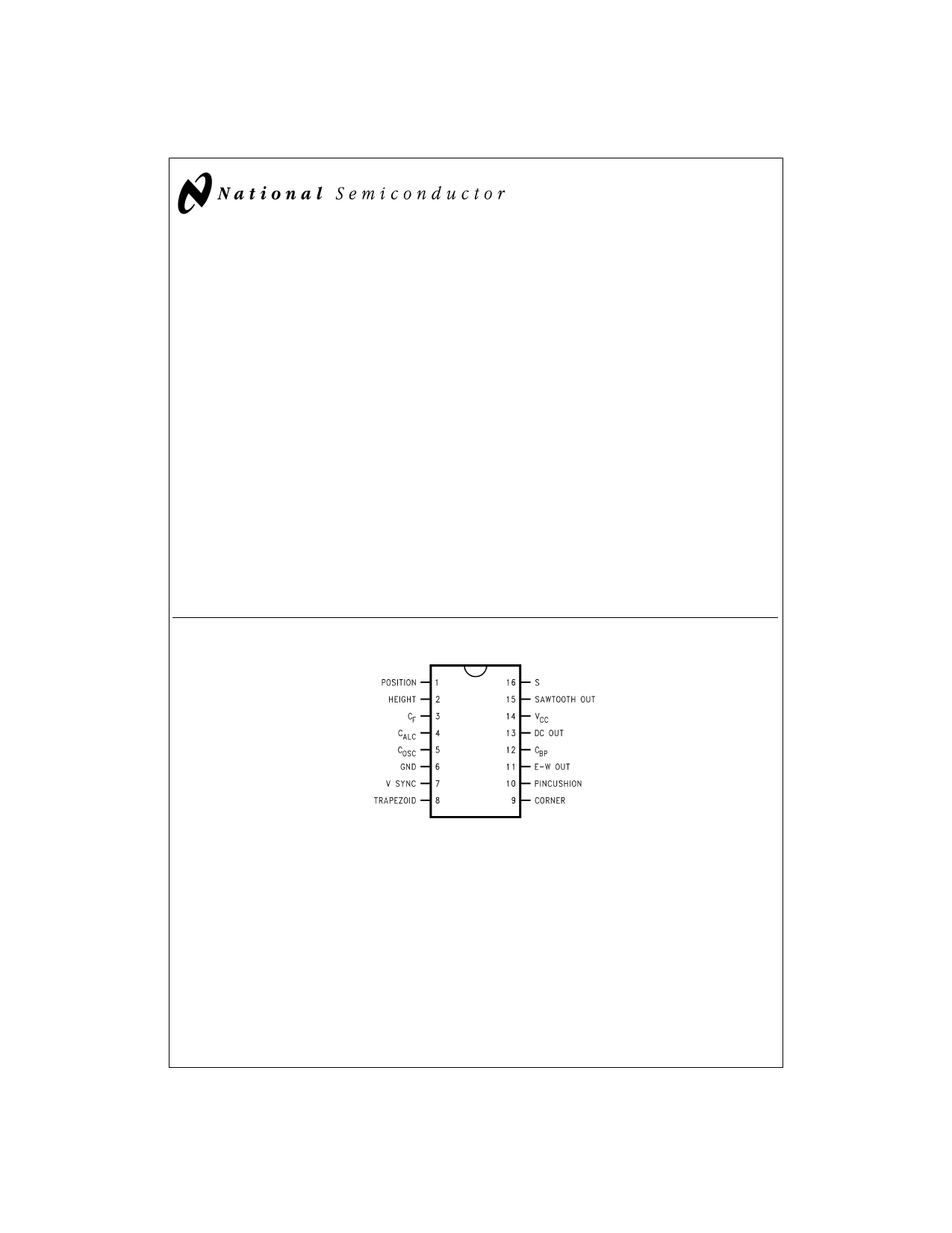
Connection Diagram
DS012894-1
FIGURE 1.
Order Number LM1296N
See NS Package Number N16A
© 1998 National Semiconductor Corporation DS012894
www.national.com
1 page 
Block Diagram
FIGURE 3.
DS012894-9
Functional Description
The LM1296 outputs a sawtooth and a variable DC voltage
for the vertical deflection amplifier. It also provides the hori-
zontal deflection output circuit with a waveform for Trap-
ezoid, Pincushion and Corner correction.
Referring to Figure 3, pin 7 (V SYNC) goes to the Sync Po-
larity Correction Block that accepts either positive-going or
negative-going sync signals. The polarity-corrected sync is
sent to the Injection-Locked Oscillator so that the sawtooth
generated is synchronized with the vertical sync. With no
sync signal AC-coupled to pin 7, the oscillator free runs at
typically 40 Hz.
There are three capacitors and one control pin connected to
the Sawtooth Waveform Generation Block. COSC is the tim-
ing capacitor for the Injection-Locked Oscillator. CF is the fil-
ter capacitor for an internal circuit that detects the existence
of vertical sync and prevents the Injection-Locked Oscillator
from locking at twice the vertical sync frequency. CALC is for
the automatic level control (ALC) circuit. The ALC circuit
maintains the sawtooth output amplitude, which is set by the
DC voltage at pin 2 (HEIGHT), regardless of the vertical sync
frequency. Since the output sawtooth goes to the geometry
correction circuit as well, the correction waveform generated
tracks the sawtooth amplitude, i.e., the height of the CRT
raster.
The S Correction block shapes the linear sawtooth into an
S-shape sawtooth. Pin 15 (SAWTOOTH OUT) outputs the
buffered S-shape sawtooth. The amount of S correction is
controlled by the DC voltage at pin 16 (S).
Referring to Figure 4, the extent of S correction is defined by
the following equation.
kS = (∆A1 + ∆A2)/2A x 100%
FIGURE 4.
DS012894-10
The LM1296 is designed to drive an external vertical deflec-
tion amplifier that is operating with positive and negative
power supplies. The LM1296 outputs an S-corrected saw-
tooth with a DC level that is typical 3.85V. Pin 13 (DC OUT)
provides a DC voltage of 3.85V ± 200 mV. By applying a DC
control voltage to pin 1 (POSITION), the output voltage at pin
13 can be varied. This sets the output DC current from the
vertical deflection amplifier, which in turn sets the raster ver-
tical position.
5 www.national.com
5 Page | ||
| Páginas | Total 10 Páginas | |
| PDF Descargar | [ Datasheet LM1296N.PDF ] | |
Hoja de datos destacado
| Número de pieza | Descripción | Fabricantes |
| LM1296 | Raster Geometry Correction System for Multi-Frequency Displays | National Semiconductor |
| LM1296 | LM1296 Raster Geometry Correction System for Multi-Frequency Displays (Rev. A) | Texas Instruments |
| LM1296N | Raster Geometry Correction System for Multi-Frequency Displays | National Semiconductor |
| Número de pieza | Descripción | Fabricantes |
| SLA6805M | High Voltage 3 phase Motor Driver IC. |
Sanken |
| SDC1742 | 12- and 14-Bit Hybrid Synchro / Resolver-to-Digital Converters. |
Analog Devices |
|
DataSheet.es es una pagina web que funciona como un repositorio de manuales o hoja de datos de muchos de los productos más populares, |
| DataSheet.es | 2020 | Privacy Policy | Contacto | Buscar |