|
|
|
PDF LM1207N Data sheet ( Hoja de datos )
| Número de pieza | LM1207N | |
| Descripción | 130 MHz/85 MHz RGB Video Amplifier System with Blanking | |
| Fabricantes | National Semiconductor | |
| Logotipo | ||
Hay una vista previa y un enlace de descarga de LM1207N (archivo pdf) en la parte inferior de esta página. Total 24 Páginas | ||
|
No Preview Available !
January 1996
LM1205 LM1207
130 MHz 85 MHz RGB Video Amplifier System with
Blanking
General Description
The LM1205 LM1207 is a very high frequency video amplifi-
er system intended for use in high resolution RGB monitor
applications In addition to the three matched video amplifi-
ers the LM1205 LM1207 contains three gated single end-
ed input black level clamp comparators for brightness con-
trol three matched DC controlled attenuators for contrast
control and three DC controlled sub-contrast attenuators
providing gain trim capability for white balance All DC con-
trol inputs offer high input impedance and an operation
range from 0V to 4V for easy interface to bus controlled
alignment systems The LM1205 LM1207 also contains a
blanking circuit which clamps the video output voltage dur-
ing blanking to within 0 1V above ground This feature pro-
vides blanking capability at the cathodes of the CRT A spot
killer is provided for CRT phosphor protection during power-
down
Features
Y Three wideband video amplifiers 130 MHz (LM1205)
b3 dB (4 VPP output)
Y Matched (g0 1 dB or 1 2%) attenuators for contrast
control
Y Three externally gated single ended input comparators
for cutoff and brightness control
Y 0V to 4V high input impedance DC contrast control
(l40 dB range)
Y 0V to 4V high input impedance DC drive control for
each video amplifier (b6 dB to 0 dB range)
Y Spot killer blanks output when VCC k 10 6V
Y Capable of 7 VPP output swing (slight reduction in
bandwidth)
Y Output stage blanking
Y Output stage directly drives most hybrid or discrete
CRT drivers
Applications
Y High resolution RGB CRT monitors
Y Video AGC amplifiers
Y Wideband amplifiers with gain and DC offset controls
Y Interface amplifiers for LCD or CCD systems
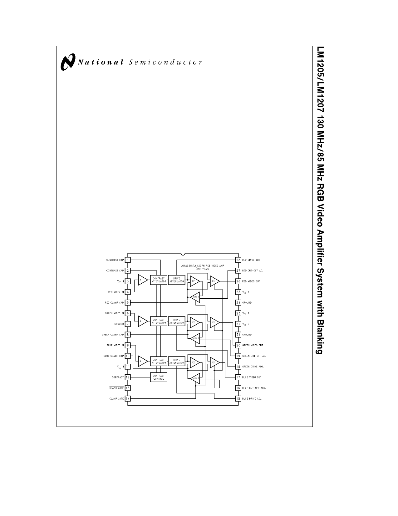
Block and Connection Diagram
C1996 National Semiconductor Corporation TL H 11881
FIGURE 1
Order Number LM1205N or LM1207N
See NS Package Number N28B
RRD-B30M66 Printed in U S A
TL H 11881 – 1
1 page 
Typical Performance Characteristics VCC e 12V TA e 25 C unless otherwise specified (Continued)
LM1207 Crosstalk vs Frequency
LM1207 Contrast vs Frequency
TL H 11881 – 7
LM1207 Drive vs Frequency
TL H 11881 – 8
TL H 11881 – 9
5 http www national com
5 Page 
Functional Description (Continued)
FIGURE 6 Block Diagram of LM1205 LM1207 Video Amplifier
TL H 11881 – 14
TL H 11881 – 15
FIGURE 7 Timing Diagram
Circuit Description
VIDEO AMPLIFIER INPUT STAGE
Figure 8 is a simplified schematic of one of the three video
amplifiers input stage along with the recommended external
components The IC pin numbers are circled and all external
components are shown outside the dashed line The video
input is applied to pin 6 via a 10 mF coupling capacitor and a
30X resistor The resistor is added to limit the current
through the input pin should an applied voltage surge rise
above VCC or drop below ground The performance of the
LM1205 LM1207 is not degraded by the 30X resistor How-
ever if EMI is a concern this resistor can be increased to
well over 100X where the rise and fall times will start to
become longer DC bias to the input pin is provided by Q5
and its associated input circuitry Z1 is a 5 6V zener that
generates the input bias voltage Q1 is a buffer to the zener
reference voltage with 5 0V generated at its emitter Q3 and
Q4 are connected as diodes Q2 is close to being a diode in
this circuit This configuration will give about 2 0V at the
collector of Q2 R2 and R3 are a voltage divider setting the
base of Q5 to about 3 5V This sets the emitter of Q5 to
about 2 8V the bias voltage of the video input This bias
voltage is necessary to assure that the entire video signal
stays within the active operating region of the LM1205
LM1207 The bias voltage goes through R6 a 20k resistor
to the video input at pin 6 R4 and R6 are of the same value
11 http www national com
11 Page | ||
| Páginas | Total 24 Páginas | |
| PDF Descargar | [ Datasheet LM1207N.PDF ] | |
Hoja de datos destacado
| Número de pieza | Descripción | Fabricantes |
| LM1207 | 130 MHz/85 MHz RGB Video Amplifier System with Blanking | National Semiconductor |
| LM1207N | 130 MHz/85 MHz RGB Video Amplifier System with Blanking | National Semiconductor |
| Número de pieza | Descripción | Fabricantes |
| SLA6805M | High Voltage 3 phase Motor Driver IC. |
Sanken |
| SDC1742 | 12- and 14-Bit Hybrid Synchro / Resolver-to-Digital Converters. |
Analog Devices |
|
DataSheet.es es una pagina web que funciona como un repositorio de manuales o hoja de datos de muchos de los productos más populares, |
| DataSheet.es | 2020 | Privacy Policy | Contacto | Buscar |