|
|
|
PDF ICX055AK Data sheet ( Hoja de datos )
| Número de pieza | ICX055AK | |
| Descripción | 1/3-inch CCD Image Sensor | |
| Fabricantes | Sony Corporation | |
| Logotipo | ||
Hay una vista previa y un enlace de descarga de ICX055AK (archivo pdf) en la parte inferior de esta página. Total 18 Páginas | ||
|
No Preview Available !
ICX055AK
ww1w./D3ata-Sihneect4hU.coCmCD Image Sensor for PAL Color Camera
For the availability of this product, please contact the sales office.
Description
The ICX055AK is an interline CCD solid-state
image sensor suitable for PAL 1/3-inch color video
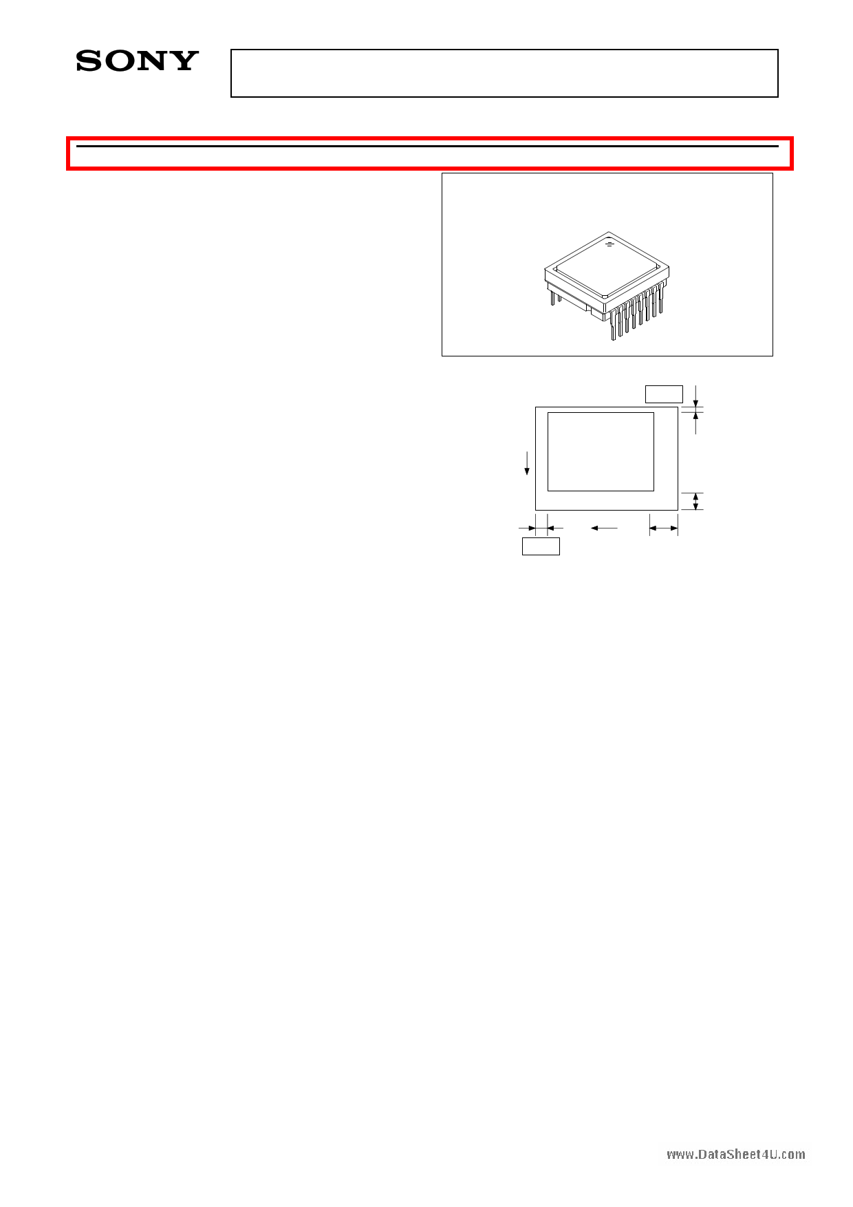
16 pin DIP (Plastic)
cameras. High sensitivity is achieved through the
adoption of Ye, Cy, Mg and G complementary color
mosaic filters and HAD (Hole-Accumulation Diode)
sensors.
This chip features a field period readout system,
and an electronic shutter with variable charge-
storage time.
Features
• High sensitivity (+3dB compare with ICX045BKA)
Pin 1
1
and low dark current
• Continuous variable-speed shutter
V
1/50s (Typ.), 1/120s to 1/10000s
• Low smear
• Excellent antiblooming characteristics
• Ye, Cy, Mg and G complementary color mosaic
filters on chip
• Horizontal register: 5V drive
7
H 30
Pin 9
Optical black position
(Top View)
14
• Reset gate:
5V drive
Device Structure
• Optical size:
1/3-inch format
• Number of effective pixels: 500 (H) × 582 (V) approx. 290K pixels
• Number of total pixels: 537 (H) × 597 (V) approx. 320K pixels
• Interline CCD image sensor
• Chip size:
6.00mm (H) × 4.96mm (V)
• Unit cell size:
9.8µm (H) × 6.3µm (V)
• Optical black:
Horizontal (H) direction: Front 7 pixels, Rear 30 pixels
Vertical (V) direction: Front 14 pixels, Rear 1 pixel
• Number of dummy bits: Horizontal 16
Vertical 1 (even field only)
• Substrate material:
Silicon
Sony reserves the right to change products and specifications without prior notice. This information does not convey any license by
any implication or otherwise under any patents or other right. Application circuits shown, if any, are typical examples illustrating the
operation of the devices. Sony cannot assume responsibility for any problems arising out of the use of these circuits.
–1–
E91Z13E66-ST
1 page 
ICX055AK
Cwlwowc.kDaEtaqSuhieveat4leUn.ctomCircuit Constant
Item
Capacitance between vertical transfer
clock and GND
Capacitance between vertical transfer
clocks
Capacitance between horizontal
transfer clock and GND
Capacitance between horizontal
transfer clocks
Capacitance between reset gate clock
and GND
Capacitance between substrate clock
and GND
Vertical transfer clock series resistor
Vertical transfer clock ground resistor
Horizontal transfer clock series resistor
Reset gate clock series resistor
Symbol
CφV1, CφV3
CφV2, CφV4
CφV12, CφV34
CφV23, CφV41
CφV13
CφV24
CφH1, CφH2
CφHH
CφRG
CφSUB
R1, R3
R2, R4
RGND
RφH
RφRG
Vφ1 Vφ2
Min. Typ. Max. Unit Remarks
1500
pF
820 pF
470 pF
230 pF
150 pF
230 pF
47 pF
47 pF
5 pF
320 pF
51 Ω
100 Ω
15 Ω
10 Ω
40 Ω
R1 CφV12
R2
CφV41
CφV1
CφV2
CφV23
CφV24
R4
CφV4 RGND CφV3
CφV34
CφV13
R3
RφH
Hφ1
CφH1
CφHH
RφH
Hφ2
CφH2
Vφ4 Vφ3
Vertical transfer clock equivalent circuit
Horizontal transfer clock equivalent circuit
RGφ
RφRG
CφRG
Reset gate clock equivalent circuit
–5–
5 Page 
ICX055AK
wwDw.eDfaintaiStihoenet4oUf.csotmandard imaging conditions
1) Standard imaging condition I:
Use a pattern box (luminance 706cd/m2, color temperature of 3200K halogen source) as a subject. (Pattern
for evaluation is not applicable.) Use a testing standard lens with CM500S (t = 1.0mm) as an IR cut filter and
image at F5.6. The luminous intensity to the sensor receiving surface at this point is defined as the
standard sensitivity testing luminous intensity.
2) Standard imaging condition II:
Image a light source (color temperature of 3200K) with a uniformity of brightness within 2% at all angles.
Use a testing standard lens with CM500S (t = 1.0mm) as an IR cut filter. The luminous intensity is adjusted
to the value indicated in each testing item by the lens diaphragm.
1. Sensitivity
Set to standard imaging condition I. After selecting the electronic shutter mode with a shutter speed of
1/250s, measure the Y signal (Ys) at the center of the screen and substitute the value into the following
formula.
S = Ys ×
250
50
[mV]
2. Saturation signal
Set to standard imaging condition II. After adjusting the luminous intensity to 10 times the intensity with
average value of the Y signal output, 200mV, measure the minimum value of the Y signal.
3. Smear
Set to standard imaging condition II. With the lens diaphragm at F5.6 to F8, adjust the luminous intensity to
500 times the intensity with average value of the Y signal output, 200mV. When the readout clock is
stopped and the charge drain is executed by the electronic shutter at the respective H blankings, measure
the maximum value YSm [mV] of the Y signal output and substitute the value into the following formula.
Sm =
YSm
200
×
1
500
×
1
10
× 100 [%] (1/10V method conversion value)
4. Video signal shading
Set to standard imaging condition II. With the lens diaphragm at F5.6 to F8, adjust the luminous intensity so
that the average value of the Y signal output is 200mV. Then measure the maximum (Ymax [mV]) and
minimum (Ymin [mV]) values of the Y signal and substitute the values into the following formula.
SHy = (Ymax – Ymin)/200 × 100 [%]
5. Uniformity between video signal channels
Set to standard imaging condition II. Adjust the luminous intensity so that the average value of the Y signal
output is 200mV, and then measure the maximum (Crmax, Cbmax [mV]) and minimum (Crmin, Cbmin
[mV]) values of the R – Y and B – Y channels of the chroma signal and substitute the values into the
following formula.
∆Sr = | (Crmax – Crmin)/200 | × 100 [%]
∆Sb = | (Cbmax – Cbmin)/200 | × 100 [%]
6. Dark signal
Measure the average value of the Y signal output (Ydt [mV]) with the device ambient temperature 60°C and
the device in the light-obstructed state, using the horizontal idle transfer level as a reference.
– 11 –
11 Page | ||
| Páginas | Total 18 Páginas | |
| PDF Descargar | [ Datasheet ICX055AK.PDF ] | |
Hoja de datos destacado
| Número de pieza | Descripción | Fabricantes |
| ICX055AK | 1/3-inch CCD Image Sensor | Sony Corporation |
| ICX055AL | 1/3-inch CCD Image Sensor | Sony Corporation |
| Número de pieza | Descripción | Fabricantes |
| SLA6805M | High Voltage 3 phase Motor Driver IC. |
Sanken |
| SDC1742 | 12- and 14-Bit Hybrid Synchro / Resolver-to-Digital Converters. |
Analog Devices |
|
DataSheet.es es una pagina web que funciona como un repositorio de manuales o hoja de datos de muchos de los productos más populares, |
| DataSheet.es | 2020 | Privacy Policy | Contacto | Buscar |