|
|
|
PDF DS1832 Data sheet ( Hoja de datos )
| Número de pieza | DS1832 | |
| Descripción | 3.3 Volt Micromonitor Chip | |
| Fabricantes | Maxim Integrated Products | |
| Logotipo | ||
Hay una vista previa y un enlace de descarga de DS1832 (archivo pdf) en la parte inferior de esta página. Total 7 Páginas | ||
|
No Preview Available !
www.DataSheet4U.com
www.dalsemi.com
DS1832
3.3-Volt MicroMonitor Chip
FEATURES
Halts and restarts an out-of-control
microprocessor
Holds microprocessor in check during power
transients
Automatically restarts microprocessor after
power failure
Monitors pushbutton for external override
Accurate 10% or 20% microprocessor power
monitoring
Eliminates need for discrete components
20% tolerance for use with 3.0-volt systems
Pin-compatible with the DS1232
Low cost 8-pin DIP, 8-pin SOIC, and space
saving µ-SOP packages available
Industrial temperature range of -40°C to
+85°C
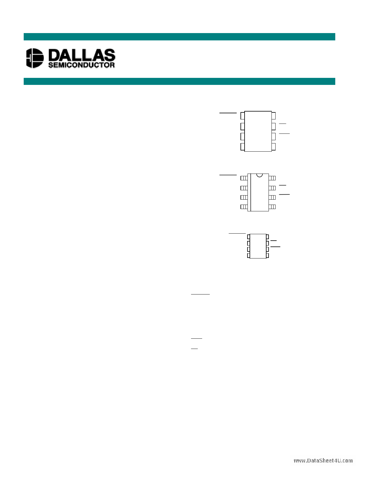
PIN ASSIGNMENT
PBRST 1
8 VCC
TD 2
7 ST
TOL 3
6 RST
GND 4
5 RST
DS1832 8-Pin DIP (300-mil)
See Mech. Drawings Section
PBRST
18
VCC
TD
27
ST
TOL
36
RST
GND
45
RST
DS1832S 8-Pin SOIC (150-mil)
See Mech. Drawings Section
PBRST
TD
TOL
GND
1
2
3
4
8 VCC
7 ST
6 RST
5 RST
DS1832µ 8-Pin µ-SOP (118-mil)
See Mech. Drawings Section
PIN DESCRIPTION
PBRST
TD
TOL
GND
RST
- Pushbutton Reset Input
- Time Delay Set
- Selects 10% or 20% VCC Detect
- Ground
- Active High Reset Output
RST - Active Low Reset Output
ST - Strobe Input
VCC - Power Supply
DESCRIPTION
The DS1832 3.3-Volt MicroMonitor monitors three vital conditions for a microprocessor: power supply,
software execution, and external override. First, a precision temperature-compensated reference and
comparator circuit monitor the status of VCC. When an out-of-tolerance condition occurs, an internal
power-fail signal is generated which forces the resets to an active state. When VCC returns to an
in-tolerance condition, the reset signals are kept in the active state for a minimum of 250 ms to allow the
power supply and processor to stabilize.
1 of 7
112099
1 page 
TIMING DIAGRAM: POWER-UP Figure 7
www.DataSheet4U.com
DS1832
RST VALID TO 0 VOLTS VCC Figure 8
OUTPUT VALID CONDITIONS
The RST output uses a push-pull output which can maintain a valid output down to 0.8 volts VCC. To sink
current below 0.8 volts a resistor can be connected from RST to Ground (see Figure 8). This arrangement
will maintain a valid value on RST during both power-up and power-down but will draw current when
RST is in the high state. A value of about 100 kΩ=should be adequate in most situations. The output with
a resistor pull-down can maintain a valid reset down to VCC equal to 0 volts.
5 of 7
5 Page | ||
| Páginas | Total 7 Páginas | |
| PDF Descargar | [ Datasheet DS1832.PDF ] | |
Hoja de datos destacado
| Número de pieza | Descripción | Fabricantes |
| DS1830 | Reset Sequence Pushbutton | Dallas Semiconductor |
| DS1830A | Reset Sequence Pushbutton | Dallas Semiconductor |
| DS1831 | Multisupply Micromonitor | Maxim Integrated Products |
| DS1831A | Multisupply Micromonitor | Maxim Integrated Products |
| Número de pieza | Descripción | Fabricantes |
| SLA6805M | High Voltage 3 phase Motor Driver IC. |
Sanken |
| SDC1742 | 12- and 14-Bit Hybrid Synchro / Resolver-to-Digital Converters. |
Analog Devices |
|
DataSheet.es es una pagina web que funciona como un repositorio de manuales o hoja de datos de muchos de los productos más populares, |
| DataSheet.es | 2020 | Privacy Policy | Contacto | Buscar |