|
|
|
PDF IRFR9220 Data sheet ( Hoja de datos )
| Número de pieza | IRFR9220 | |
| Descripción | Power MOSFET ( Transistor ) | |
| Fabricantes | Vishay Siliconix | |
| Logotipo | ||
Hay una vista previa y un enlace de descarga de IRFR9220 (archivo pdf) en la parte inferior de esta página. Total 11 Páginas | ||
|
No Preview Available !
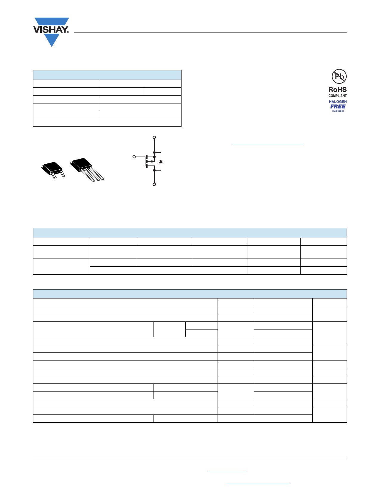
IRFR9220, IRFU9220, SiHFR9220, SiHFU9220
www.vishay.com
Vishay Siliconix
Power MOSFET
PRODUCT SUMMARY
VDS (V)
RDS(on) ()
Qg (Max.) (nC)
Qgs (nC)
Qgd (nC)
Configuration
- 200
VGS = - 10 V
20
3.3
11
Single
1.5
S
DPAK
(TO-252)
D
IPAK
(TO-251)
D
G
GS
GD S
D
P-Channel MOSFET
FEATURES
• Dynamic dV/dt Rating
• Repetitive Avalanche Rated
• Surface Mount (IRFR9220, SiHFR9220)
• Straight Lead (IRFUFU9220, SiHFU9220)
• Available in Tape and Reel
• P-Channel
• Fast Switching
• Material categorization: For definitions of compliance
please see www.vishay.com/doc?99912
DESCRIPTION
Third power MOSFETs technology is the key to Vishay
advanced line of Power MOSFET transistors. The efficient
geometry and unique processing of the Power MOSFETs
design achieve very low on-state resistance combined with
high transconductance and extreme device ruggedness.
The DPAK is designed for surface mounting using vapor
phase, infrared, or wave soldering techniques. The straight
lead version (IRFU, SiHFU series) is for through-hole
mounting applications. Power dissipation levels up to 1.5 W
are possible in typical surface mount applications.
ORDERING INFORMATION
Package
DPAK (TO-252)
DPAK (TO-252)
DPAK (TO-252)
DPAK (TO-252)
Lead (Pb)-free and
Halogen-free
Lead (Pb)-free
SiHFR9220-GE3
IRFR9220PbF
SiHFR9220-E3
SiHFR9220TRL-GE3a
IRFR9220TRLPbFa
SiHFR9220TL-E3a
SiHFR9220TRR-GE3a
IRFR9220TRRPbFa
SiHFR9220TR-E3a
SiHFR9220TR-GE3a
IRFR9220TRPbFa
SiHFR9220T-E3a
Note
a. See device orientation.
ABSOLUTE MAXIMUM RATINGS (TC = 25 °C, unless otherwise noted)
PARAMETER
SYMBOL
LIMIT
Drain-Source Voltage
Gate-Source Voltage
Continuous Drain Current
Pulsed Drain Currenta
Linear Derating Factor
Linear Derating Factor (PCB Mount)e
Single Pulse Avalanche Energyb
Repetitive Avalanche Currenta
Repetitive Avalanche Energya
Maximum Power Dissipation
Maximum Power Dissipation (PCB Mount)e
Peak Diode Recovery dV/dtc
VGS at - 10 V
TC = 25 °C
TC = 100 °C
VDS
VGS
ID
IDM
TC = 25 °C
TA = 25 °C
EAS
IAR
EAR
PD
dV/dt
- 200
± 20
- 3.6
- 2.3
- 14
0.33
0.020
310
- 3.6
4.2
42
2.5
- 5.0
Operating Junction and Storage Temperature Range
Soldering Recommendations (Peak Temperature)d
for 10 s
TJ, Tstg
Notes
a. Repetitive rating; pulse width limited by maximum junction temperature (see fig. 11).
b. VDD = - 50 V, Starting TJ = 25 °C, L = 35 mH, Rg = 25 , IAS = - 3.6 A (see fig. 12).
c. ISD - 3.9 A, dI/dt 95 A/μs, VDD VDS, TJ 150 °C.
d. 1.6 mm from case.
e. When mounted on 1" square PCB (FR-4 or G-10 material).
- 55 to + 150
260
IPAK (TO-251)
SiHFU9220-GE3
IRFU9220PbF
SiHFU9220-E3
UNIT
V
A
W/°C
mJ
A
mJ
W
V/ns
°C
S13-0166-Rev. E, 04-Feb-13
1
Document Number: 91283
For technical questions, contact: [email protected]
THIS DOCUMENT IS SUBJECT TO CHANGE WITHOUT NOTICE. THE PRODUCTS DESCRIBED HEREIN AND THIS DOCUMENT
ARE SUBJECT TO SPECIFIC DISCLAIMERS, SET FORTH AT www.vishay.com/doc?91000
1 page 
IRFR9220, IRFU9220, SiHFR9220, SiHFU9220
www.vishay.com
Vishay Siliconix
VDS
VGS
Rg
RD
D.U.T.
- 10 V
Pulse width ≤ 1 µs
Duty factor ≤ 0.1 %
-
+VDD
Fig. 10a - Switching Time Test Circuit
Fig. 9 - Maximum Drain Current vs. Case Temperature
VGS
10 %
td(on) tr
td(off) tf
90 %
VDS
Fig. 10b - Switching Time Waveforms
Fig. 11 - Maximum Effective Transient Thermal Impedance, Junction-to-Case
S13-0166-Rev. E, 04-Feb-13
5
Document Number: 91283
For technical questions, contact: [email protected]
THIS DOCUMENT IS SUBJECT TO CHANGE WITHOUT NOTICE. THE PRODUCTS DESCRIBED HEREIN AND THIS DOCUMENT
ARE SUBJECT TO SPECIFIC DISCLAIMERS, SET FORTH AT www.vishay.com/doc?91000
5 Page 
www.vishay.com
Legal Disclaimer Notice
Vishay
Disclaimer
ALL PRODUCT, PRODUCT SPECIFICATIONS AND DATA ARE SUBJECT TO CHANGE WITHOUT NOTICE TO IMPROVE
RELIABILITY, FUNCTION OR DESIGN OR OTHERWISE.
Vishay Intertechnology, Inc., its affiliates, agents, and employees, and all persons acting on its or their behalf (collectively,
“Vishay”), disclaim any and all liability for any errors, inaccuracies or incompleteness contained in any datasheet or in any other
disclosure relating to any product.
Vishay makes no warranty, representation or guarantee regarding the suitability of the products for any particular purpose or
the continuing production of any product. To the maximum extent permitted by applicable law, Vishay disclaims (i) any and all
liability arising out of the application or use of any product, (ii) any and all liability, including without limitation special,
consequential or incidental damages, and (iii) any and all implied warranties, including warranties of fitness for particular
purpose, non-infringement and merchantability.
Statements regarding the suitability of products for certain types of applications are based on Vishay’s knowledge of typical
requirements that are often placed on Vishay products in generic applications. Such statements are not binding statements
about the suitability of products for a particular application. It is the customer’s responsibility to validate that a particular
product with the properties described in the product specification is suitable for use in a particular application. Parameters
provided in datasheets and/or specifications may vary in different applications and performance may vary over time. All
operating parameters, including typical parameters, must be validated for each customer application by the customer’s
technical experts. Product specifications do not expand or otherwise modify Vishay’s terms and conditions of purchase,
including but not limited to the warranty expressed therein.
Except as expressly indicated in writing, Vishay products are not designed for use in medical, life-saving, or life-sustaining
applications or for any other application in which the failure of the Vishay product could result in personal injury or death.
Customers using or selling Vishay products not expressly indicated for use in such applications do so at their own risk. Please
contact authorized Vishay personnel to obtain written terms and conditions regarding products designed for such applications.
No license, express or implied, by estoppel or otherwise, to any intellectual property rights is granted by this document or by
any conduct of Vishay. Product names and markings noted herein may be trademarks of their respective owners.
Material Category Policy
Vishay Intertechnology, Inc. hereby certifies that all its products that are identified as RoHS-Compliant fulfill the
definitions and restrictions defined under Directive 2011/65/EU of The European Parliament and of the Council
of June 8, 2011 on the restriction of the use of certain hazardous substances in electrical and electronic equipment
(EEE) - recast, unless otherwise specified as non-compliant.
Please note that some Vishay documentation may still make reference to RoHS Directive 2002/95/EC. We confirm that
all the products identified as being compliant to Directive 2002/95/EC conform to Directive 2011/65/EU.
Vishay Intertechnology, Inc. hereby certifies that all its products that are identified as Halogen-Free follow Halogen-Free
requirements as per JEDEC JS709A standards. Please note that some Vishay documentation may still make reference
to the IEC 61249-2-21 definition. We confirm that all the products identified as being compliant to IEC 61249-2-21
conform to JEDEC JS709A standards.
Revision: 02-Oct-12
1 Document Number: 91000
11 Page | ||
| Páginas | Total 11 Páginas | |
| PDF Descargar | [ Datasheet IRFR9220.PDF ] | |
Hoja de datos destacado
| Número de pieza | Descripción | Fabricantes |
| IRFR9220 | Power MOSFET ( Transistor ) | IRF |
| IRFR9220 | P Channel Power MOSFET | Intersil |
| IRFR9220 | Power MOSFET ( Transistor ) | Vishay Siliconix |
| Número de pieza | Descripción | Fabricantes |
| SLA6805M | High Voltage 3 phase Motor Driver IC. |
Sanken |
| SDC1742 | 12- and 14-Bit Hybrid Synchro / Resolver-to-Digital Converters. |
Analog Devices |
|
DataSheet.es es una pagina web que funciona como un repositorio de manuales o hoja de datos de muchos de los productos más populares, |
| DataSheet.es | 2020 | Privacy Policy | Contacto | Buscar |