|
|
|
PDF SC4519H Data sheet ( Hoja de datos )
| Número de pieza | SC4519H | |
| Descripción | 3A Step-Down Switching Regulator | |
| Fabricantes | Semtech Corporation | |
| Logotipo | ||
Hay una vista previa y un enlace de descarga de SC4519H (archivo pdf) en la parte inferior de esta página. Total 14 Páginas | ||
|
No Preview Available !
POWER MANAGEMENT
Description
The SC4519H is a current mode switching regulator with
an integrated switch, operating at 600kHz with separate
sync and enable functions. The integrated switch allows
for cost effective low power solutions (peak switch current
3 amps). The sync function allows customers to
synchronize to a faster clock in order to avoid frequency
beating in noise sensitive applications. High frequency
of operation allows for very small passive components.
www.DataCaSnhuedreret4innUst.ctmoamnotdaenoepoeursatdiountyalcloycwles
for fast dynamic
adjustment as
response
the input
varies (ideal for CPE applications where the input is a
wall plug power).
The low shutdown current makes it ideal for portable
applications where battery life is important.
SC4519H
600kHz, 3A Step-Down
Switching Regulator
Features
Integrated 3 Amp switch
600kHz frequency of operation
Current mode controller
Synchronizable to higher frequency up to 1.2MHz
Precision enable threshold
SO-8 EDP package. Lead free product, fully WEEE
and RoHS compliant
Applications
XDSL modems
CPE equipment
DC-DC point of load applications
Portable equipment
The SC4519H is a 600kHz switching regulator
synchronizable to a faster frequency from 750kHz to
1.2MHz.
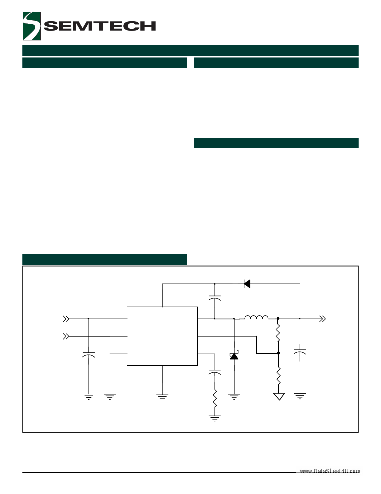
Typical Application Circuit
D1
VIN
Enable
C3
2 IN
5 EN
1
BST
SW 3
SC4519H
FB 6
8 SYNC
GND
4
COMP 7
C4
C1
L1
D2
R3
VOUT
R1
C2
R2
Revision: September 11, 2007
1
www.semtech.com
1 page 
POWER MANAGEMENT
Pin Configurations
TOP VIEW
BST
IN
SW
www.DataSheet4UG.coNmD
1
2
3
4
8 SYNC
7 COMP
6 FB
5 EN
(SO-8 EDP)
SC4519H
Ordering Information
Part Number (1)(2)
Package
SC4519HSETRT
SO-8 EDP
SC4519HEVB
EVALUATION BOARD
Notes:
(1) Only available in tape and reel packaging. A reel
contains 2500 devices.
(2) Lead free product. This product is WEEE and
RoHS compliant.
Pin Descriptions
Pin # Pin Name Pin Function
1 BST This pin provides power to the internal NPN switch. The minimum turn on voltage for this switch
is 2.7V.
2 IN Pin IN delivers all power required by control and power circuitry. This pin sees high di/dt during
switching. A decoupling capacitor should be attached to this pin as close as possible.
3 SW Pin SW is the emitter of the internal switch. The external freewheeling diode should be connected
as close as possible to this pin.
4 GND All voltages are measured with respect to this pin. The decoupling capacitor and the freewheeling
diode should be connected to GND as short as possible.
5 EN This is the chip enable input. The regulator is switched on if EN is high, and it is off if EN is low.
The regulator is in standby mode when EN is low, and the input supply current is reduced to a few
microamperes.
6 FB Feedback input for adjustable output controllers.
7 COMP This is the output of the internal error amplifier and input of the peak current comparator. A
compensation network is connected to this pin to achieve the specified performance.
8 SYNC This is synchronous control pin used to synchronize the internal oscillator to an external pulse
control signal. When not used, it should be connected to GND.
- THERMAL Pad for heatsinking purposes. Connect to ground plane using multiple vias. Not connected
PAD internally.
2007 Semtech Corp.
5
www.semtech.com
5 Page 
SC4519H
POWER MANAGEMENT
Application Information (Cont.)
Mag Layout Guidelines:
ωp1
www.DataSheet4U.com
ωZ
Loop gain T(s)
Power stage
ωC ωP2
ω
Figure 4. Asymptotic diagrams of power stage with
current loop closed and its loop gain.
The design guidelines for the SC4519H applications are
as following:
1. Set the loop gain crossover corner frequency ωC for
given switching corner frequency ωC = 2πfC
2. Place an integrator at the origin to increase DC and
low frequency gains.
3. Select ωZ such that it is placed at ωP1 to obtain a
-20dB/dec rate to go across the 0dB line.
4. Place a high frequency compensator pole
ωP2 (ωP2 = πfs) to get the maximum attenuation of
the switching ripple and high frequency noise with
the adequate phase lag at ωC.
In order to achieve optimal electrical and thermal
performance for high frequency converters, special
attention must be paid to the PCB layouts. The goal of
layout optimization is to identify the high di/dt loops and
minimize them. The following guidelines should be used
to ensure proper operation of the converters.
1. A ground plane is suggested to minimize switching
noises and trace losses and maximize heat
transferring.
2. Start the PCB layout by placing the power components
first. Arrange the power circuit to achieve a clean
power flow route. Put all power connections on one
side of the PCB with wide copper filled areas if
possible.
3. The VIN bypass capacitor should be placed next to
the VIN and GND pins.
4. The trace connecting the feedback resistors to the
output should be short, direct and far away from any
noise sources such as switching node and switching
components.
5. Minimize the loop including input capacitor, the
SC4519H and freewheeling diode D2. This loop
passes high di/dt current. Make sure the trace width
is wide enough to reduce copper losses in this loop.
6. Maximize the trace width of the loop connecting the
inductor, freewheeling diode D2 and the output
capacitor.
7. Connect the ground of the feedback divider and the
compensation components directly to the GND pin
of the SC4519H by using a separate ground trace.
8. Connect Pin 4 to a large copper area to remove the
IC heat and increase the power capability of the
SC4519H. A few feedthrough holes are required to
connect this large copper area to a ground plane to
further improve the thermal environment of the
SC4519H. The traces attached to other pins should
be as wide as possible for the same purpose.
2007 Semtech Corp.
11
www.semtech.com
11 Page | ||
| Páginas | Total 14 Páginas | |
| PDF Descargar | [ Datasheet SC4519H.PDF ] | |
Hoja de datos destacado
| Número de pieza | Descripción | Fabricantes |
| SC4519 | 3A Step-Down Switching Regulator | Semtech Corporation |
| SC4519H | 3A Step-Down Switching Regulator | Semtech Corporation |
| Número de pieza | Descripción | Fabricantes |
| SLA6805M | High Voltage 3 phase Motor Driver IC. |
Sanken |
| SDC1742 | 12- and 14-Bit Hybrid Synchro / Resolver-to-Digital Converters. |
Analog Devices |
|
DataSheet.es es una pagina web que funciona como un repositorio de manuales o hoja de datos de muchos de los productos más populares, |
| DataSheet.es | 2020 | Privacy Policy | Contacto | Buscar |