|
|
|
PDF CAT813 Data sheet ( Hoja de datos )
| Número de pieza | CAT813 | |
| Descripción | (CATxxx) Supervisory Circuits | |
| Fabricantes | Catalyst Semiconductor | |
| Logotipo | ||
Hay una vista previa y un enlace de descarga de CAT813 (archivo pdf) en la parte inferior de esta página. Total 14 Páginas | ||
|
No Preview Available !
µP Supervisory Circuits
CAT705, CAT706, CAT813
FEATURES
Accurate under voltage system monitoring
R¯¯E¯S¯E¯T¯ guaranteed valid for VCC = 1.0V
6µA supply current
www.DataSheet4U.c2om00ms RESET pulse width
Watchdog timer function 1.6 sec timeout
Brownout detection system reset for use with
3.0, 3.6, and 5.0 volt systems
Pin and function compatible with the
MAX705/706/813L products
Operating Range from -40°C to +85°C
Available in SOIC 8-lead and MSOP 8-lead
packages
APPLICATIONS
Microprocessor and microcontroller based
systems
Intelligent instruments
Control systems
Critical µP monitors
Portable equipment
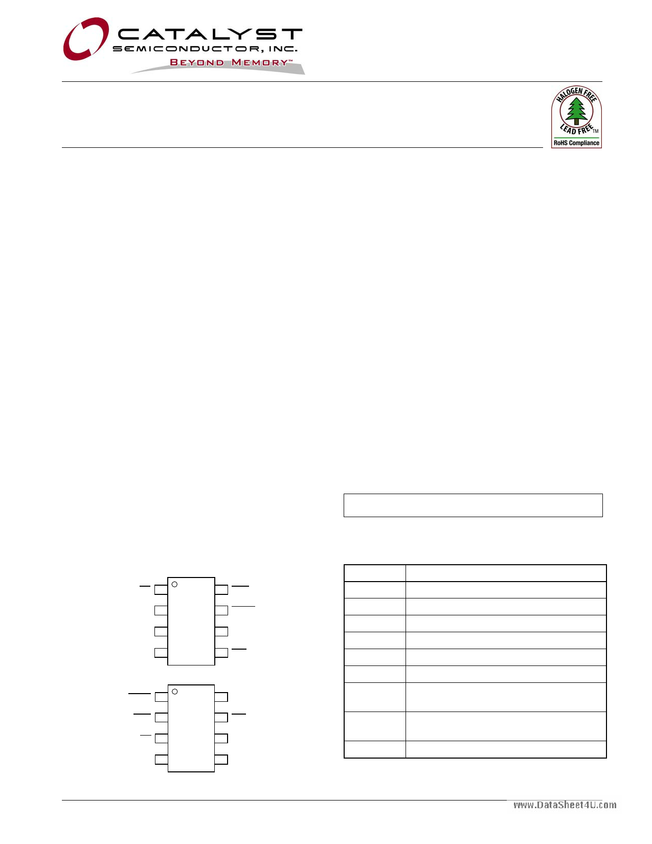
PIN CONFIGURATION
SOIC 8-Lead
MR 1
8 WDO
VCC 2
GND 3
7 RESET
(RESET for CAT813)
6 WDI
PFI 4
5 PFO
MSOP 8-Lead
RESET
(RESET for CAT813)
WDO
1
2
8 WDI
7 PFO
MR 3
6 PFI
VCC 4
5 GND
DESCRIPTION
The CAT705, CAT706, and CAT813 provide reset and
monitoring functions for the electronic systems. Each
device monitors the system voltage and maintains a
reset output until that voltage reaches the device’s
specified trip value and then maintains the reset
output active condition until the device’s internal timer
allows the system power supply to stabilize.
The CAT705, CAT706, and CAT813 have a watchdog
input which can be used to monitor a system signal
and cause a reset to be issued if the signal fails to
change state prior to a timeout condition.
The CAT705 and CAT706 provide a manual R¯¯E¯S¯E¯T¯
input which initiate reset if pulled low. The CAT705,
CAT706 and CAT813 provide a RESET output which
is low for the CAT705 and CAT706, but high for the
CAT813.
There is a secondary supply monitor included for
power-fail warning (pin PFI).
The CAT706 has a threshold voltage 4.40V. The
CAT705/ CAT813 have a threshold voltage of 4.65V.
For Ordering Information details, see page 13.
PIN FUNCTIONS
Pin Name
¯M¯R¯
VCC
GND
PFI
¯P¯F¯O¯
WDI
R¯¯E¯S¯E¯T¯
RESET
¯W¯¯D¯O¯
Function
Manual Reset input
Power Supply
Ground
Power Fail voltage monitor Input.
Power Fail Output
Watchdog Timer Input
CMOS Push-Pull Active Low Reset
Output (CAT705 & CAT706)
CMOS Push-Pull Active High Reset
Output (CAT813)
Watchdog Timer Output
© Catalyst Semiconductor, Inc.
Characteristics subject to change without notice
1
Doc. No. MD-3030, Rev. A
1 page 
CAT705, CAT706, CAT813
ELECTRICAL OPERATING CHARACTERISTICS (continued)
VCC = 4.50V to 5.5V for CAT705, CAT706 & CAT813 versions;
VCC = 3.0V to 3.6V for the CAT706 R/S/T version,
-40°C ≤ TA ≤ +85°C unless otherwise noted.
Typical values at TA = 25°C and VCC = 5V for CAT705, CAT706, & CAT813 versions;
VCC = 3.3V for the CAT706 T/S versions; VCC = 3.0V for the CAT706 R version.
Symbol Parameter
Conditions
WATCHDOG INPUT (CAT705, CAT706 & CAT813)
tWD Watchdog Timeout Period
tWDI WDI Pulse Width
VIL = 0.4V, VIH = 0.8 x VCC
VIL
www.DataSheet4U.comVIH
WDI Input Voltage(3)
WDI Input Current(4)
WDI = VCC, Time Average
WDI = 0V, Time Average
WDO Output Voltage
ISOURCE = -800µA
ISINK = 1.2mA
MANUAL RESET INPUT(CAT705, CAT706 & CAT813)
VIL
VIH
¯M¯R¯ Input Voltage
¯M¯R¯ Pull-up Current
¯M¯R¯ = 0V
tPB
tPDLY
¯M¯R¯ Pulse Width
¯M¯R¯ low to Reset Delay(5)
PFI Input Threshold
VCC = 5V
PFI Input Current
¯P¯F¯O¯ Output Voltage
ISOURCE = -800µA
ISINK = 3.2mA
Min Typ Max Units
1.00
50
0.7 x VCC
-150
VCC – 1.5
1.60
2.25
0.3 x VCC
50
-50
VCC – 0.25
0.1
150
0.4
s
ns
V
µA
V
0.7 x VCC
40
1
1.2
-25
VCC - 1.5V
70
1.25
0.01
0.3 x VCC
V
140 µA
µs
5 µs
1.3 V
25 nA
V
0.4 V
Notes:
(3) WDI is internally serviced within the watchdog period if WDI is left open.
(4) The WDI input current is specified as an average input current when the WDI input is driven high or low. The WDI input if connected to a
three-stated output device can be disabled in the tristate mode as long as the leakage current is less than 10µA and a maximum
capacitance of less than 200pF. To clock the WDI input in the active mode the drive device must be able to source or sink at least 200µA
when active.
(5) R¯¯E¯S¯E¯T¯ for CAT705 & CAT706 & RESET for CAT813.
© Catalyst Semiconductor, Inc.
Characteristics subject to change without notice
5
Doc. No. MD-3030, Rev. A
5 Page 
PACKAGE OUTLINE DRAWING
MSOP 8-Lead 3.0 x 3.0mm (Z) (1) (2)
www.DataSheet4U.com
E E1
TOP VIEW
A A2
A1
D
e
SIDE VIEW
b
c
CAT705, CAT706, CAT813
SYMBOL
A
A1
A2
b
c
D
E
E1
e
L
L1
L2
θ
MIN
0.05
0.75
0.22
0.13
2.90
4.80
2.90
0.40
0º
NOM
0.10
0.85
3.00
4.90
3.00
0.65 BSC
0.60
0.95 REF
0.25 BSC
MAX
1.10
0.15
0.95
0.38
0.23
3.10
5.00
3.10
0.80
6º
END VIEW
DETAIL A
θ
L2
L
L1
DETAIL A
For current Tape and Reel information, download the PDF file from:
http://www.catsemi.com/documents/tapeandreel.pdf.
Notes:
(1) All dimensions are in millimeters. Angles in degrees.
(2) Complies with JEDEC MO-187
© Catalyst Semiconductor, Inc.
Characteristics subject to change without notice
11
Doc. No. MD-3030, Rev. A
11 Page | ||
| Páginas | Total 14 Páginas | |
| PDF Descargar | [ Datasheet CAT813.PDF ] | |
Hoja de datos destacado
| Número de pieza | Descripción | Fabricantes |
| CAT810 | 3-Pin Microprocessor Power Supply Supervisors | ON Semiconductor |
| CAT810 | (CAT803 - CAT810) 3-Pin Microprocessor Power Supply Supervisors | Catalyst Semiconductor |
| CAT811 | 4-Pin Microprocessor Power Supply Supervisors | Catalyst Semiconductor |
| CAT811EUS-T | 4-Pin Microprocessor Power Supply Supervisors | Catalyst Semiconductor |
| Número de pieza | Descripción | Fabricantes |
| SLA6805M | High Voltage 3 phase Motor Driver IC. |
Sanken |
| SDC1742 | 12- and 14-Bit Hybrid Synchro / Resolver-to-Digital Converters. |
Analog Devices |
|
DataSheet.es es una pagina web que funciona como un repositorio de manuales o hoja de datos de muchos de los productos más populares, |
| DataSheet.es | 2020 | Privacy Policy | Contacto | Buscar |